310
9.4.6
Input Capture Setting
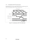
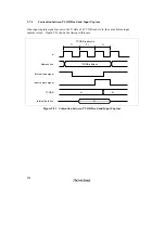
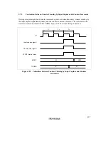
The 8TCNT value can be transferred to TCORB on detection of an input edge on the input
capture/output compare pin (TMIO
1
or TMIO
3
). Rising edge, falling edge, or both edge detection
can be selected. In 16-bit count mode, 16-bit input capture can be used.
Setting Input Capture Operation in 8-Bit Timer Mode (Normal Operation)
•
Channel 1:
Set TCORB1 as an 8-bit input capture register with the ICE bit in 8TCSR1.
Select rising edge, falling edge, or both edges as the input edge(s) for the input capture
signal (TMIO
1
) with bits OIS3 and OIS2 in 8TCSR1.
Select the input clock with bits CKS2 to CKS0 in 8TCR1, and start the 8TCNT count.
•
Channel 3:
Set TCORB3 as an 8-bit input capture register with the ICE bit in 8TCSR3.
Select rising edge, falling edge, or both edges as the input edge(s) for the input capture
signal (TMIO
3
) with bits OIS3 and OIS2 in 8TCSR3.
Select the input clock with bits CKS2 to CKS0 in 8TCR3, and start the 8TCNT count.
Note:
When TCORB1 in channel 1 is used for input capture, TCORB0 in channel 0 cannot be
used as a compare match register.
Similarly, when TCORB3 in channel 3 is used for input capture, TCORB2 in channel 2
cannot be used as a compare match register.
Setting Input Capture Operation in 16-Bit Count Mode
•
Channels 0 and 1:
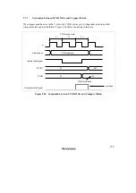
In 16-bit count mode, TCORB0 and TCORB1 function as a 16-bit input capture register
when the ICE bit is set to 1 in 8TCSR1.
Select rising edge, falling edge, or both edges as the input edge(s) for the input capture
signal (TMIO
1
) with bits OIS3 and OIS2 in 8TCSR0. (In 16-bit count mode, the settings of
bits OIS3 and OIS2 in 8TCSR1 are ignored.)
Select the input clock with bits CKS2 to CKS0 in 8TCR1, and start the 8TCNT count.
•
Channels 2 and 3:
In 16-bit count mode, TCORB2 and TCORB3 function as a 16-bit input capture register
when the ICE bit is set to 1 in 8TCSR3.
Select rising edge, falling edge, or both edges as the input edge(s) for the input capture
signal (TMIO
3
) with bits OIS3 and OIS2 in 8TCSR2. (In 16-bit count mode, the settings of
bits OIS3 and OIS2 in 8TCSR3 are ignored.)
Select the input clock with bits CKS2 to CKS0 in 8TCR3, and start the 8TCNT count.
Содержание H8/3060
Страница 10: ......
Страница 16: ......
Страница 114: ...66 ...
Страница 132: ...84 ...
Страница 144: ...96 ...
Страница 170: ...122 ...
Страница 212: ...164 ...
Страница 268: ...220 ...
Страница 332: ...284 ...
Страница 396: ...348 ...
Страница 494: ...446 ...
Страница 698: ...650 ...
Страница 729: ...681 H8 3062F ZTAT or H8 3062F ZTAT R mask version Ports 1 2 5 LED 600 Ω Figure 22 5 Sample LED Circuit ...
Страница 748: ...700 H8 3064F ZTAT B mask version Ports 1 2 5 LED 600 Ω Figure 22 8 Sample LED Circuit ...
Страница 777: ...729 H8 3062F ZTAT B mask version Ports 1 2 5 LED 600 Ω Figure 22 14 Sample LED Circuit ...
Страница 810: ...762 ...
Страница 994: ...946 ...


