469
15.1.3
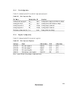
Pin Configuration
Table 15.1 summarizes the D/A converter's input and output pins.
Table 15.1
D/A Converter Pins
Pin Name
Abbreviation I/O
Function
Analog power supply pin
AV
SS
Input
Analog power supply and reference voltage
Analog ground pin
AV
SS
Input
Analog ground and reference voltage
Analog output pin 0
DA
0
Output
Analog output, channel 0
Analog output pin 1
DA
1
Output
Analog output, channel 1
Reference voltage input pin
V
REF
Input
Analog reference voltage
15.1.4
Register Configuration
Table 15.2 summarizes the D/A converter's registers.
Table 15.2
D/A Converter Registers
Address
*
Name
Abbreviation
R/W
Initial Value
H'FFF9C
D/A data register 0
DADR0
R/W
H'00
H'FFF9D
D/A data register 1
DADR1
R/W
H'00
H'FFF9E
D/A control register
DACR
R/W
H'1F
H'EE01A
D/A standby control register
DASTCR
R/W
H'FE
Note:
*
Lower 20 bits of the address in advanced mode
Содержание H8/3060
Страница 10: ......
Страница 16: ......
Страница 114: ...66 ...
Страница 132: ...84 ...
Страница 144: ...96 ...
Страница 170: ...122 ...
Страница 212: ...164 ...
Страница 268: ...220 ...
Страница 332: ...284 ...
Страница 396: ...348 ...
Страница 494: ...446 ...
Страница 698: ...650 ...
Страница 729: ...681 H8 3062F ZTAT or H8 3062F ZTAT R mask version Ports 1 2 5 LED 600 Ω Figure 22 5 Sample LED Circuit ...
Страница 748: ...700 H8 3064F ZTAT B mask version Ports 1 2 5 LED 600 Ω Figure 22 8 Sample LED Circuit ...
Страница 777: ...729 H8 3062F ZTAT B mask version Ports 1 2 5 LED 600 Ω Figure 22 14 Sample LED Circuit ...
Страница 810: ...762 ...
Страница 994: ...946 ...


