4.
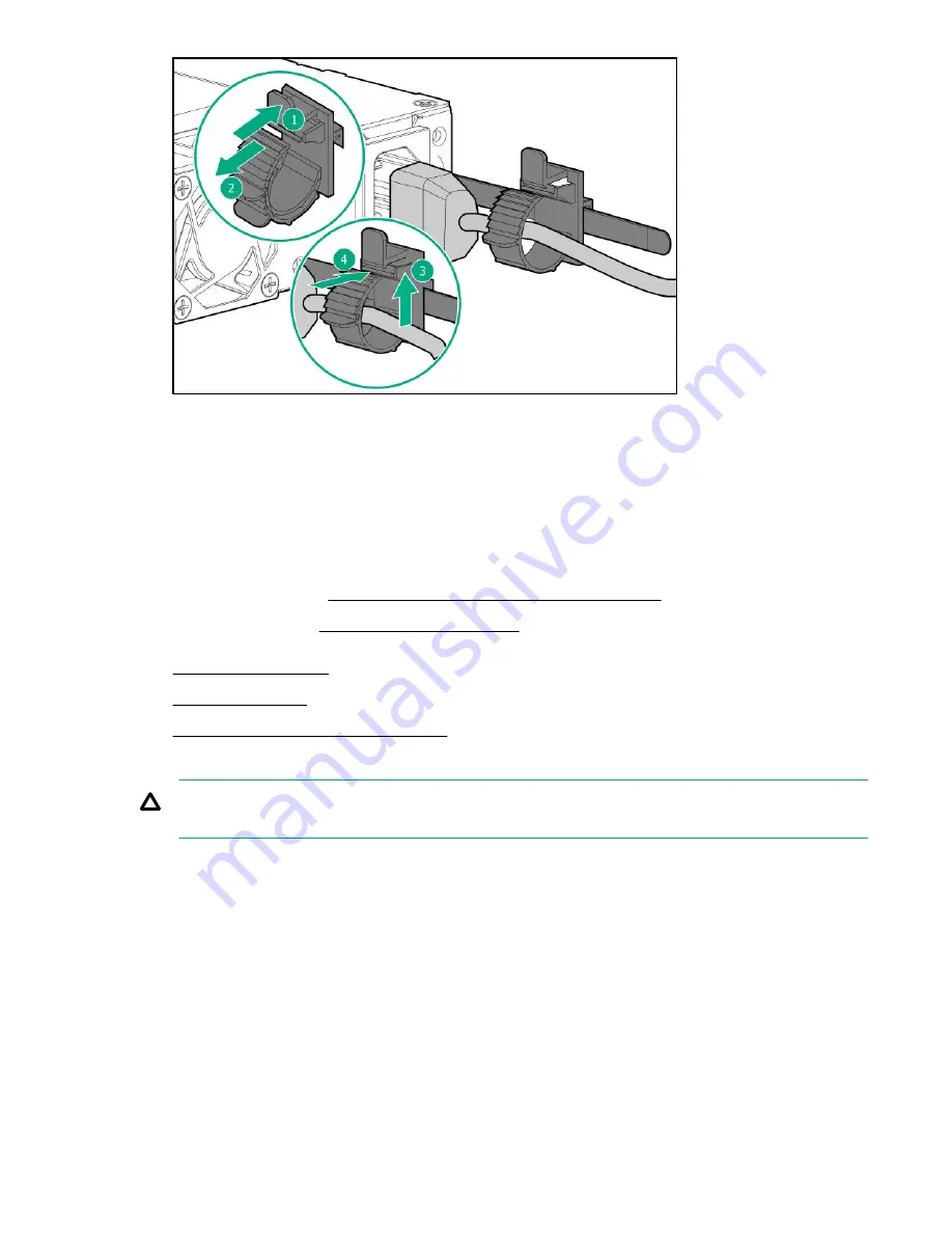
Remove all power:
a. Disconnect each power cord from the power source.
b. Disconnect each power cord from the server.
5.
Disconnect all peripheral cables from the server.
6.
Do one of the following:
Position the tower server for hardware configuration.
• Server in rack mode:
Extend the server from the rack.
7.
8.
9.
Observe the guidelines for managing cables.
CAUTION: The snap-in latch of the energy pack holder is flexible. However, to avoid damaging this latch, do not
apply too much pressure on this latch when removing or installing the energy pack from the chassis.
10. Remove the energy pack holder:
a. If an energy pack is installed, disconnect the energy pack cable.
b. While carefully holding the snap-in latch in the open position, slide the energy pack holder up to disengage it
from the chassis.
148
Hardware options installation
Содержание ProLiant ML350 Gen10
Страница 26: ...SFF drive bay numbering Smart Array controller Tower orientation Rack orientation 26 Component identification ...
Страница 27: ...SFF drive bay numbering SAS expander Tower orientation Rack orientation Component identification 27 ...
Страница 28: ...NVMe drive bay numbering Tower orientation Rack orientation 28 Component identification ...
Страница 31: ...Component identification 31 ...
Страница 33: ...Open the front bezel Procedure 1 Unlock the front bezel 2 Open the front bezel Operations 33 ...
Страница 55: ...10 Secure the rear end of rack rails to the rack columns with the rear shipping screws Operations 55 ...
Страница 178: ...Cable color Description Blue Front I O cable Orange Front USB cable 178 Cabling ...


