


84
ADL500 • Quick installation guide - Specifications and connection
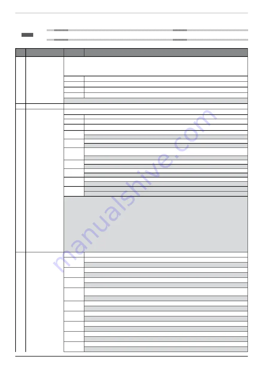
10.3 Messages
Note !
For more information see chapter
Index
Error message shown on
the display
Sub-code
Description
1
Load default param
Condition:
may occur during loading of the parameter database saved in flash
normally appears in the following conditions: at initial power-on when a new firmware version is downloaded, when the regulation is installed on a new
size, when the region is changed.
If this message is displayed when the drive is already operating, this means that a problem has occurred in the parameter database saved in Flash.
If this message is displayed, the drive automatically performs the
Load default
command.
0001H-1
The database saved is not valid
0002H-2
The database saved is not compatible
0003H-3
The database saved refers to a different size from the current size
0004H-4
The database saved refers to a different region from the current region
Solution:
Set the parameters to the value required and perform
Save parameter
2...4
Not used
5
Autotune (motor)
Condition:
this may occur during the self-tuning procedure
0
No error
1
N.A.
2
N.A.
3
The motor plate data parameters have changed but the
Take parameters
command, PAR 2020, has not been executed
Solution:
Execute the
Take parameters
command.
4
The motor is not connected
Solution:
Connect the motor
5
While running self-tuning the ESC key was pressed or the enable contact was opened or an alarm occurred. The self-tuning command
was sent with the drive in the alarm condition
Solution:
Eliminate the reason for the alarm, remove the reason for the opening of the enable contact, reset alarms.
6
A self-tuning measurement is beyond the drive limits.
Solution:
Check the motor plate data or drive and motor sizes have been combined incorrectly.
7
The self-tuning command was sent without being enabled.
Solution:
Close the enable contact before sending the self-tuning command
8 ... 21
A self-tuning measurement has reached a drive limit.
Solution:
Check the motor plate data or the drive and motor sizes have been combined incorrectly.
30
The Enable was not given or removed in time during the phasing procedure.
Solution:
Repeat the phasing procedure and check the connection of the enable signals.
Solution:
If the message appears with a value other than 0, follow the instructions supplied for each particular case and repeat self-tuning. This should
be performed using the wizard function available from the keypad (STARTUP WIZARD) and the Tool software on the PC.
Pay attention to all motor plate data parmaeters, especially:
-
Rated speed
,
Motor rated speed
in rpm.
•
(ADL500 for Asynchronous motor) Take care not to set the
Rated speed
parameter to the synchronous speed. The value of the
Rated speed
parameter must be less than: [(
Rated frequency
* 60) /
Pole pairs
].
•
(ADL500 for Synchronous motor) Take care to set the
Rated speed
parameter to the synchronous speed.
-
Rated frequency
,
Motor rated frequency
in Hz
-
Pole pairs
,
Motor pole pairs
If the problem persists even after following the instructions supplied, confirm the values of the motor plate data parameters, execute the
Take param-
eters
command but not self-tuning.
5
Autotune
0
No error
(phasing)
40
The encoder card in use cannot manage automatic phasing.
(Only Synchronous)
Solution:
Use the appropriate encoder card
41
Incorrect Incremental encoder impulse count
Solution:
Check the electric signals of the incremental encoder. Check the value of the encoder impulse parameter
42
Incorrect absolute encoder impulse count
Solution:
Check the electric signals of the absolute encoder. Check the configuration of the absolute encoder
43
Incorrect incremental encoder impulse count or incorrect absolute encoder impulse count probably caused by an incorrect value of the
pole pairs parameter or a load applied to the motor.
Solution:
Check the value of the pole pairs parameter, check whether a load is applied
44
Incorrect incremental encoder impulse count probably caused by the incorrect value of the encoder impulse parameter.
Solution:
Check the electric signals of the incremental encoder. Check the value of the encoder impulse parameter.
45
Incorrect absolute encoder impulse count
Solution:
Check the electric signals of the absolute encoder. Check the configuration of the absolute encoder.
46
Incremental encoder impulse count sign inverted with respect to the absolute encoder impulse count.
Solution:
Invert the A+ and A- signal of the incremental encoder.
47
Incremental encoder impulse count sign inverted with respect to the absolute encoder impulse count.
Solution:
Invert the A+ and A- signal of the absolute encoder.
48
Incorrect phase sequence. (Message not signalled)
Solution:
The automatic procedure has modified the setting of the Encoder direction parameter. No other action is required
Содержание ADL500
Страница 95: ......