


14
ADL500 • Quick installation guide - Specifications and connection
4.4.3 Torque control
Torque resolution (*) ____________________ > 0.1 %
Torque control precision (*) ______________ Flux vector CL with feedback: ± 3%, Flux vector OL with feedback:: ± 6%,
Direct torque control ____________________ yes
Current limitation _______________________ Limits ±, Mot/gen limits, Variable limits
(*) referred to rated torque
4.4.4 Current rating
Overload _____________________________
ADL550
: 183% *10 sec e 200% * 2 sec (output frequency from 0 Hz)
ADL530 and ADL510
: 183% *10 sec (output frequency from 0 Hz)
Overload Cycle characteristics: current 0Hz: 1 p.u. of rated output current for 1 s, OL max: 2 p.u. of the rated
output current for 2 s, Total cycle duration: 18 s (corresponding to 200 cycle hours), CDF (Cyclic duration fac-
tor - Cycle S4 IEC 60034-1): 40%.
Switching frequency ____________________ 10 kHz (4-5-8-10 kHz)
The switching frequency is managed by the control algorithm in relation to the drive temperature.
4.5 Input electrical data
Input voltage U
ln
_______________________
ADL550
: three-phase 230 - 380 - 400 - 460 - 480 Vac -15%+10%
ADL530
: three-phase 230 - 380 - 400 - 460 - 480 Vac -15%+10%
ADL510
: three-phase 380 - 400 Vac -15%+10%
Maximum input voltage unbalance _________ 3 %
Connection to TT and TN Networks _________ yes, standard version
Connection to IT Networks or Regenerative ___ only on request (*), please contact the Gefran Customer Service.
Choke _______________________________ Sizes 1...2: Optional (DC or AC)
Note!
See chapter "5.2 Input chokes" on page 18 for THD values in accordance with EN 12015 and for selection of external inductances.
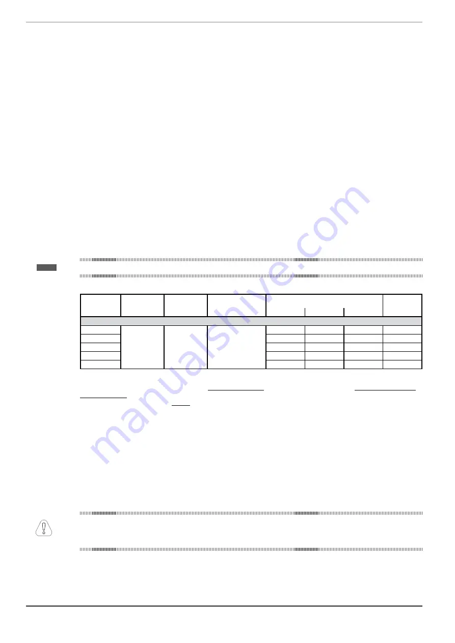
S
ize
Input
frequency
Overvoltage
threshold
Undervoltage
threshold
e
ffectiVe
input
current
i
n
(@ i
n
out
)
DC-Link
Capacity
(Hz)
(Vdc)
(Vdc)
@ 230 Vac (A)
@ 400 Vac (A)
@ 480 Vac (A)
(µF)
ADL5..-...-4 , 3ph
1040
50/60 Hz, ± 2%
820 Vdc
@ 480 Vac = 470 Vdc
@ 460 Vac = 450 Vdc
@ 400 Vac = 391 Vdc
@ 380 Vac = 371 Vdc
@ 230 Vac = 225 Vdc
12
11
10
470
1055
17
16
15
680
1075
23
22
20
680
2110
31
29
26
1020
2150
42
40
37
1500
(*) ADL500 can only operate on IT networks devoid of any faults (between active parts and PE) or in the presence of
temporary faults.
Therefore an insulation monitor MUST be used to detect and enable prompt removal of any fault condition.
Insulation monitor
Since the ADL500 drive is normally used in a ground-insulated system (IT), in accordance with IEC 61557-8, use of
insulation resistance monitoring is required.
The monitoring system must be able to detect insulation loss, both on the AC and DC power supply sides and on the
motor side.
A ground fault must be promptly detected and removed as quickly as possible to avoid damage to either the inverter
or the entire system as a unit (in the event of insulation loss, the drive must be immediately disabled and disconnected
from power sources).
The insulation monitor must be selected on a case-by-case basis according to the power supply, connection system
and type of drive.
Recommended insulation monitors e.g.: see the BENDER © ISOMETER® line.
The insulation monitor must be plugged into the main power supply (if ADL500 is AC powered) or the DC side (if
ADL300 is DC-powered).
The insulation monitor alarm threshold should be set to the highest possible resistance value.
Attention
Содержание ADL500
Страница 95: ......