


32
ADL500 • Quick installation guide - Specifications and connection
ADL510
ADL530
ADL550
Asynchronous
Brushless
SSC OL
(1)
Flux Vector OL
(1)
Flux Vector CL
(1)
Flux Vector CL
(1)
Incremental digital
Yes
Yes
Yes
-
-
Recommended
Possibile
Incremental sinusoidal
Yes
Yes
Yes
-
-
Recommended
Possibile
Incremental sinu
absolute SinCos
-
Yes
(2)
Yes
-
-
Possible
Recommended
Incremental sinu
Absolute Endat
-
Yes
(2)
Yes
-
-
Possible
Recommended
Absolute Endat
-
Yes
Yes
-
-
Possible
Recommended
Absolute Biss
-
Yes
Yes
-
-
Possible
Recommended
(1) PAR 540
Control type.
(2) ADL530: "freeze" not available.
- = encoder not used
Encoders must be fitted to the motor shaft using anti-backlash couplings. The best control is achieved with configura
-
tions that have incremental sinusoidal channels.
For electrical connections always use good quality cables with shielded twisted pairs, according to the procedures and
specifications described in the following paragraphs.
The configuration parameters for each encoder can be found in the
ENCODER.
In the event of an encoder malfunction the drive generates the
Speed fbk back loss
alarm and the cause of the mal-
function is shown in parameter 2172
SpdFbkLoss code
.
If the encoder is not used by the regulation algorithm the drive still manages the encoder position reading but does not
generate an alarm in case of malfunctioning.
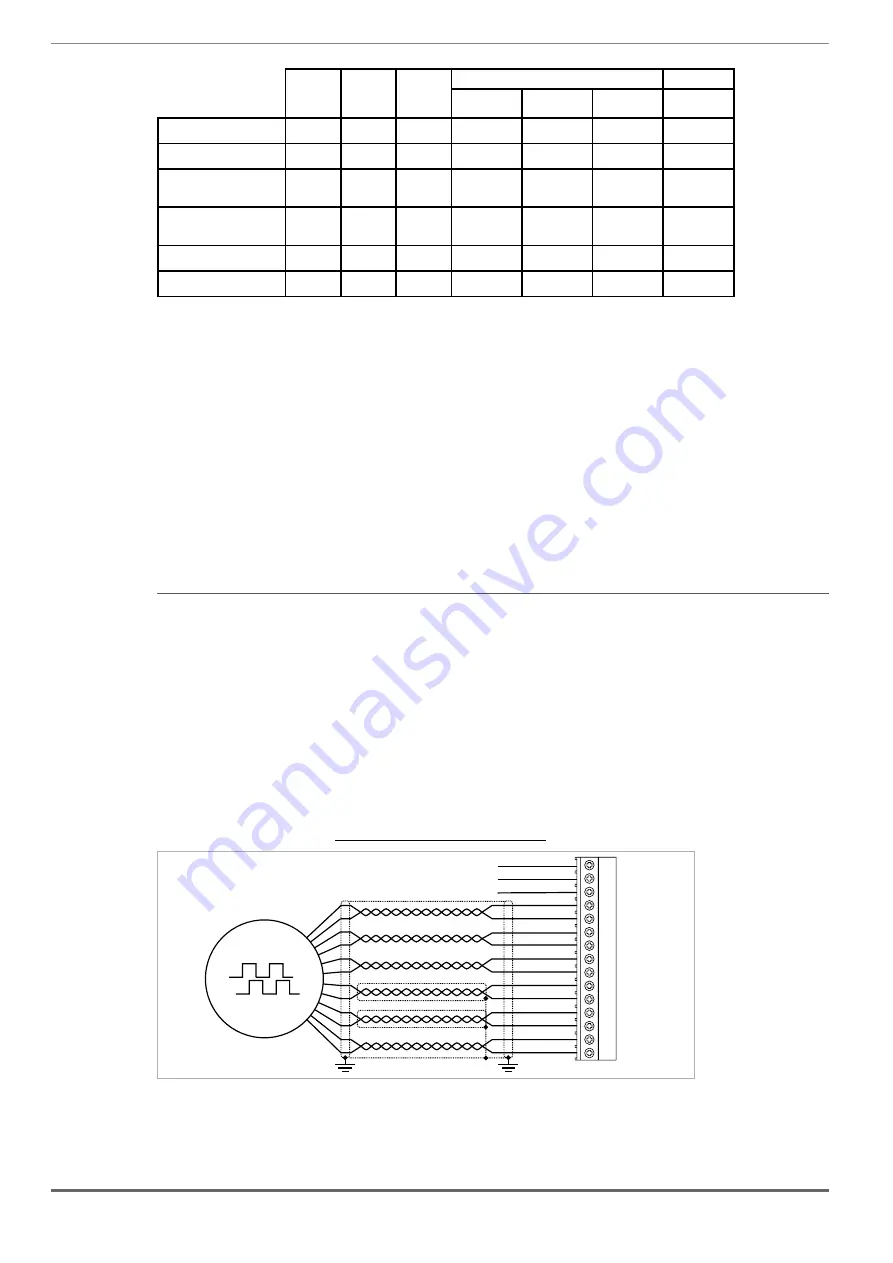
(1) Connection SinCos encoder (ADL510, ADL530) - Connection SinCos e 2 Freeze (ADL550)
Technical specification
Channels _______________________________ A+ A-, B+ B-, Z+ Z-, Sin+ Sin-, Cos+ Cos-, differential
Management of loss of encoder signals.
Max frequency __________________________ 200 kHz (check the number of encoder impulses according to the maximum speed)
Electrical interface ________________________
Channels A/B/Sin/Cos 0.6 V ≤ Vpp ≤ 1.2 V (typ. 1.0 V) − Channel Z* 0.2 V ≤ Vpp ≤
0.8 V
Load capacity ___________________________
Channels A/B/Z* 8 mA @ 1.0 Vpp (Zin 120Ω)
Channels Sin/Cos 1 mA @ 1.0 Vpp (Zin 1kΩ)
Programmable internal power supply __________ min +5.2 V, max +20V
(d 5.2 V) − Imax 150 mA.
The internal power supply of the encoder can be selected from the keypad (ENCODER menu,
parameter
Encoder supply
(PAR 2102) to balance the loss of voltage due to the length of the
encoder cable and load current.
PAR 2102
Encoder supply,
range: min=5.2V, max=20V, step of 0.1V; default=5.2V.
Cable length ____________________________ max 50m
* Channel Z = I (Index mark)
Figure 7.3.3: Connection SinCos e 2 Freeze
COS-
COS+
SIN-
SIN+
A-
A+
0VE out
+VE out
Z-
Z+
B-
B+
8
9
10
11
12
13
14
15
1
2
3
4
5
6
7
(*)
XE
Fast input 2 (**)
Fast input 1 (**)
0V Fast input (**)
(*) Connection of shielding, see figure 7.3.
2
(**) on ADL550 only
Содержание ADL500
Страница 95: ......