


CHAPTER 5: SETTINGS
GROUPED ELEMENTS
L60 LINE PHASE COMPARISON SYSTEM – INSTRUCTION MANUAL
5-243
5
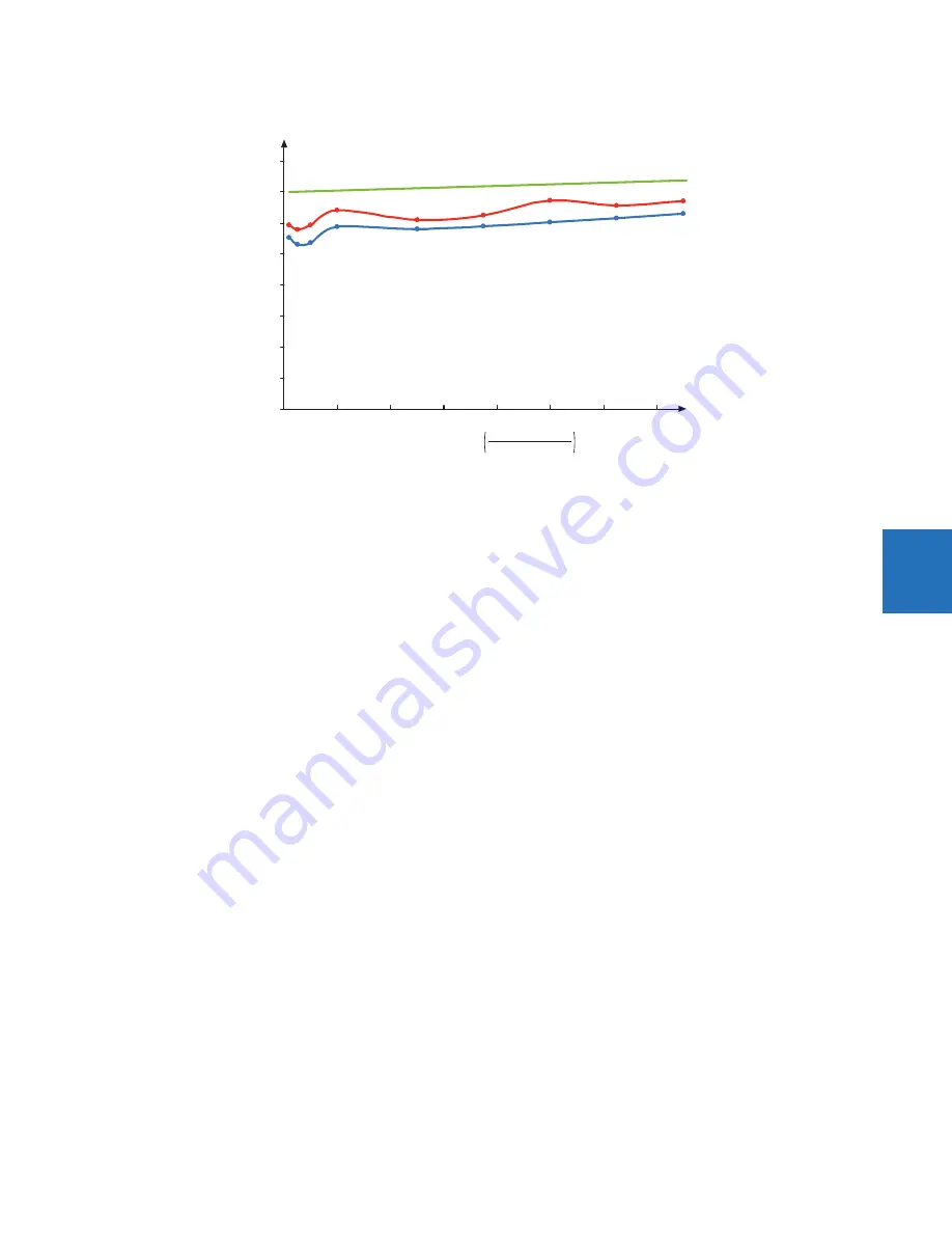
Figure 5-132: Breaker failure overcurrent supervision reset time
Settings
BF1 MODE
— This setting is used to select the breaker failure operating mode: single or three pole.
BF1 USE AMP SUPV
— If set to "Yes," the element is initiated if current flowing through the breaker is above the supervision
pickup level.
BF1 USE SEAL-IN
— If set to "Yes," the element is sealed-in if current flowing through the breaker is above the supervision
pickup level.
BF1 3-POLE INITIATE
— This setting selects the FlexLogic operand that initiates three-pole tripping of the breaker.
BF1 PH AMP SUPV PICKUP
— This setting is used to set the phase current initiation and seal-in supervision level. Generally this
setting detects the lowest expected fault current on the protected breaker. It can be set as low as necessary (lower than
breaker resistor current or lower than load current)—high-set and low-set current supervision guarantee correct
operation.
BF1 N AMP SUPV PICKUP
— This setting is used to set the neutral current initiate and seal-in supervision level. Generally this
setting detects the lowest expected fault current on the protected breaker. Neutral current supervision is used only in the
three phase scheme to provide increased sensitivity. This setting is valid only for three-pole tripping schemes.
BF1 USE TIMER 1
— If set to "Yes," the early path is operational.
BF1 TIMER 1 PICKUP DELAY
— Timer 1 is set to the shortest time required for breaker auxiliary contact Status-1 to open, from
the time the initial trip signal is applied to the breaker trip circuit, plus a safety margin.
BF1 USE TIMER 2
— If set to "Yes," the main path is operational.
BF1 TIMER 2 PICKUP DELAY
— Timer 2 is set to the expected opening time of the breaker, plus a safety margin. This safety
margin was historically intended to allow for measuring and timing errors in the breaker failure scheme equipment. In
microprocessor relays this time is not significant. In L60 relays, which use a Fourier transform, the calculated current
magnitude ramps-down to zero one power frequency cycle after the current is interrupted, and this lag needs to be
included in the overall margin duration, as it occurs after current interruption. The Breaker Failure Main Path Sequence
figure that follows shows a margin of two cycles; this interval is considered the minimum appropriate for most
applications.
Note that in bulk oil circuit breakers, the interrupting time for currents less than 25% of the interrupting rating can be
significantly longer than the normal interrupting time.
BF1 USE TIMER 3
— If set to "Yes," the Slow Path is operational.
BF1 TIMER 3 PICKUP DELAY
— Timer 3 is set to the same interval as timer 2, plus an increased safety margin. Because this
path is intended to operate only for low level faults, the delay can be in the order of 300 to 500 ms.
836769A4.CDR
0
0.2
0.4
0.6
0.8
0
20
40
60
80
100
120
140
Average
Maximum
Margin
Mul
WL
ple of pickup
fault current
threshold setting
Br
eaker
failur
e
reset
time
(cycles)
Содержание L60
Страница 130: ...4 30 L60 LINE PHASE COMPARISON SYSTEM INSTRUCTION MANUAL LOGIC DIAGRAMS CHAPTER 4 INTERFACES 4 ...
Страница 464: ...5 334 L60 LINE PHASE COMPARISON SYSTEM INSTRUCTION MANUAL TESTING CHAPTER 5 SETTINGS 5 ...
Страница 498: ...7 10 L60 LINE PHASE COMPARISON SYSTEM INSTRUCTION MANUAL TARGETS MENU CHAPTER 7 COMMANDS AND TARGETS 7 ...
Страница 570: ...10 14 L60 LINE PHASE COMPARISON SYSTEM INSTRUCTION MANUAL DISPOSAL CHAPTER 10 MAINTENANCE 10 ...
Страница 582: ...A 12 L60 LINE PHASE COMPARISON SYSTEM INSTRUCTION MANUAL FLEXANALOG ITEMS APPENDIX A FLEXANALOG OPERANDS A ...
Страница 588: ...C 4 L60 LINE PHASE COMPARISON SYSTEM INSTRUCTION MANUAL REVISION HISTORY APPENDIX C MISCELLANEOUS C ...
Страница 592: ...iv L60 LINE PHASE COMPARISON SYSTEM INSTRUCTION MANUAL ABBREVIATIONS ...


