600-SERIES HARDWARE MANUAL
Appendix M - 635-600 Series Boards
M.5
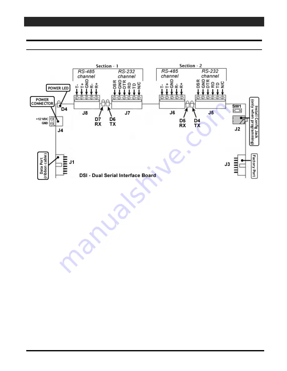
DSI Board– Dual Serial Interface board
Component List:
[J1]
I
2C Data Buss:
port to connect to the data
ribbon
cable.
[SW 1] Power Reset Switch -
power reset
[J2] Config Jack:
(when jack plug is installed at the time of power reset, board is in Config mode)
[J3] Factory Port:
factory use
[J4] Power connector: +
12 VDC board power connects from the wiring harness
[J5] RS-232 port for Section 2:
wiring contacts
for an RS-232 channel (future release)
[J6] RS-485 port for Section 2:
wiring contacts
for an RS-485 channel
[D4] TX LED for Section 2:
may flicker when data is transmitted
[D5] RX LED for Section 2:
may flicker when data is transmitted
[J7] RS-232 port for Section 1:
wiring contacts
for an RS-232 channel (future release)
[J8] RS-485 port for Section 1:
wiring contacts
for an RS-485 channel
[D4] TX LED for Section 1:
may flicker when data is transmitted
[D5] RX LED for Section 1:
may flicker when data is transmitted
[D4] Power LED:
indicates power is applied to the DPI board.
IMPORTANT:
. You cannot use both com channels on the same section at the same time. You must choose to
use either the 485 or the 232 channel on a section. You can use Section-1 as 485 and section-2 as 232.
APPENDIX-Page
M-5


