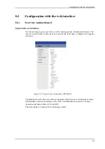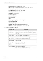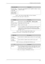
Configuration with the web interface
:
5-21
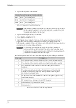
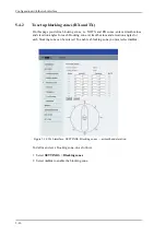
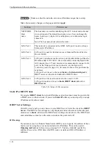
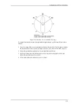
3. Enter start and stop azimuth value in degrees for the blocking zone. Values allowed: 0
to 360 degrees. Enter clockwise.
4. Enter the start and stop elevation angle for the blocking zone. If you enter nothing,
there will be no blocking zone. Values allowed: -90 to 90 degrees.
5. Select
No TX
for zones if you don’t want the system to transmit.
Figure 5-15: Blocking zone, example: 315 - 45 degrees
Figure 5-16: Blocking zone, example: 45 - 315 degrees
Important
You must enter 2 different elevation angles to have an
active blocking zone.
$QWHQQD
%ORFNLQJ]RQH
$QWHQQD
%ORFNLQJ]RQH
Содержание FV-110GX
Страница 1: ...GX TERMINAL FV 110GX OPERATOR S MANUAL www furuno com Model ...
Страница 16: ...xiv This page is intentionally left blank ...
Страница 46: ...Installation of the ADU 2 22 N connector interface on the ADU ...
Страница 54: ...To connect the ADU ACU and GMU 2 30 This page is intentionally left blank ...
Страница 110: ...Installation check list Functional test in harbor 6 4 This page is intentionally left blank ...
Страница 135: ...Alternative ground for steel hulls A 5 Figure A 3 Grounding at a dedicated RF ground alternative ...
Страница 164: ...Supported commands C 10 This page is intentionally left blank ...
Страница 165: ...D 1 Appendix D Approvals D This appendix lists the approvals for FV 110GX OEM declaration ...
Страница 166: ...OEM declaration D 2 D 1 OEM declaration ...
Страница 173: ...OD 1 30 Jul 2018 H MAKI ...
Страница 174: ...OD 2 30 Jul 2018 H MAKI ...
Страница 175: ...OD 3 2 Oct 2018 H MAKI ...
Страница 176: ...OD 4 2 Oct 2018 H MAKI ...
Страница 178: ......
Страница 186: ......


