Calibration
:
5-11
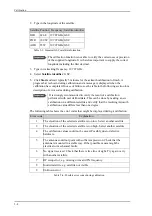
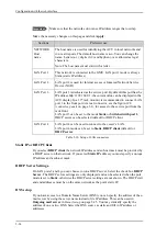
Satellite identifier: GSC, NID, Orbital position (DVB-S, DVB-S2)
1
. See also Table 5-
3 on page 5-8.
6. Click
Apply
to save the settings for this satellite profile for calibration. The system is
ready for the azimuth calibration.
7. Click
Start
to start the azimuth calibration.
5.3.3
Cable calibration
1. In the section
TX cable calibration
, select the
Type
:
• Cable calibration: The system will make a complete cable calibration
(recommended).
• Disabled: The gain is set at a maximum and no cable calibration is made. It is up to
the modem to make the necessary adjustments.
2. On the page
SERVICE > Calibration
click
Start
in the section
TX cable
calibration
.
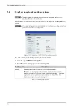
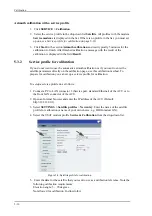
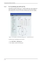
Figure 5-9: Web interface: SERVICE, Calibration, cable attenuator margin
3. Wait for the calibration to finish. After finished calibration a message with the result
of the calibration is displayed in the field
Result
.This screen shows how much
attenuation margin is left for the antenna cable. This indicates whether the antenna
cable and connectors are in good condition and well crimped.
It is recommended to make a cable calibration when servicing the system to check if
the antenna cable is still in good order.
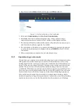
4. After the azimuth and cable calibration switch on the modem. It will automatically
make a BUC calibration and is then ready.
5. When commissioning is completed, test all subscribed services, see
Installation check
list: Functional test in harbor
on page 6-3.
1. Use Orbital position and NID if you want to use NID or orbital position or other KA band
satellites with DVB-S2 support. The DVB symbol rate must be >5 Ms/s. For NID use
preferably a unique NID (ONID). An azimuth calibration without NID can be useful in
regions where the satellite operators do not broadcast NID (US, China, Australia etc.). For
NID=0 the NID is not used when checking the satellite link. For NID 1 to 65535 the
supplied NID is matched against the Network ID broadcast by the satellite. For orbital
position the supplied longitude is matched with the orbital position broadcast by the
satellite. Not all service providers broadcast the orbital position.
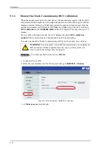
Important
Make sure that the modem is not switched on at this point. The modem can
be switched on after the cable calibration.
Make sure that
Heading
,
Mode
on the page
SETTINGS > Navigation
is
set to
Fixed
or
External
.
Important
If there is no input from the vessel’s gyro compass: Change the heading
input setting from
Fixed
to
None
at
Heading
–
Input
.
Fixed heading is not allowed for sailing vessels!
Содержание FV-110GX
Страница 1: ...GX TERMINAL FV 110GX OPERATOR S MANUAL www furuno com Model ...
Страница 16: ...xiv This page is intentionally left blank ...
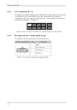
Страница 46: ...Installation of the ADU 2 22 N connector interface on the ADU ...
Страница 54: ...To connect the ADU ACU and GMU 2 30 This page is intentionally left blank ...
Страница 110: ...Installation check list Functional test in harbor 6 4 This page is intentionally left blank ...
Страница 135: ...Alternative ground for steel hulls A 5 Figure A 3 Grounding at a dedicated RF ground alternative ...
Страница 164: ...Supported commands C 10 This page is intentionally left blank ...
Страница 165: ...D 1 Appendix D Approvals D This appendix lists the approvals for FV 110GX OEM declaration ...
Страница 166: ...OEM declaration D 2 D 1 OEM declaration ...
Страница 173: ...OD 1 30 Jul 2018 H MAKI ...
Страница 174: ...OD 2 30 Jul 2018 H MAKI ...
Страница 175: ...OD 3 2 Oct 2018 H MAKI ...
Страница 176: ...OD 4 2 Oct 2018 H MAKI ...
Страница 178: ......
Страница 186: ......


