background image

10

Kongsberg C-series

10.  

System Setup

10.1.  Introduction

This chapter will explain functions and parameters that are important for the 

C system

 to run

properly.
It is a supplement to the information available from the 

User Manual for i-cut Production

Console

.

Examine each step carefully to ensure proper settings:

One time adjustments completed at the factory

The functions are included here as a reference.
They are not used during normal operation.
If necessary, they should be repeated, as indicated in the function description.

1

Adjust X1 to X2 Angle

2

Register Table Size

3

Adjust Measuring Station Position

4

Set Ruler Position

5

Set Main Reference Point

6

Map Table Top Surface

7

Calibrate Foot on Measuring Station

8

Vacuum Setup

9

Router Setup

Adjustments to customize the table

1

Select Reference Point

52

Содержание Kongsberg C series

Страница 1: ...Kongsberg C series User Manual 05 2018 C series ...

Страница 2: ...inition of Use 16 5 5 Warning Sign Explanation 17 5 6 Attention Areas 19 5 6 1 Moving Parts Laser Radiation and High Voltage 19 5 6 2 Loose Clothing 19 5 6 3 Noise Level 19 5 6 4 Ejection of Parts 20 5 6 5 i Camera strobing light 20 5 7 Safety Devices 21 5 7 1 Overview 21 5 7 2 Emergency Stop Button 21 5 7 3 Yellow Black tape 22 5 7 4 Warning Lamp on top of Y carriage 23 5 7 5 DynaGuard Safety Sys...

Страница 3: ...acuum Zone Selection 42 8 8 Job Execution 43 8 9 Corrugated Production 44 8 10 Milling Production 44 8 11 Make a Pen Plot 44 9 How To Procedures Advanced 45 9 1 Cutting Thick Materials 45 9 2 Hard Board Production 45 9 3 Multi Pass Creasing or Milling 46 9 4 Jobs including Reverse Operations 47 9 5 Work with different Reference Point Settings 48 9 6 MultiZone Production 48 9 6 1 MultiZone Workflow...

Страница 4: ...ool Height Calibration 70 11 6 Rotation Adjustment for Rotating tools 70 11 7 Center Offset Adjustment 71 11 8 Tool Offset 72 11 9 Maintain Tool List 73 12 Tooling System 75 12 1 Introduction 75 12 2 Tool Handling and Care 75 12 3 How to Replace a Tool 76 12 4 Two or more tools of the same type 76 12 5 Measuring Station 77 12 6 HDU Heavy Duty Unit 78 12 6 1 Crease Wheel ø150 mm 79 12 6 2 V notch K...

Страница 5: ...4 12 10 1 Introduction 124 12 10 2 Startup 125 12 10 3 Error Conditions 125 12 11 VibraCut 126 12 12 Rigid Material Knife RM Knife Tool 129 12 13 HiForce Knife 130 12 14 Psaligraphy Knife 132 12 15 PressCut 134 12 16 RotaCut 137 12 17 Braille Tool 140 12 18 CorruSpeed Knife 145 12 18 1 Tool adjustment 147 12 19 Braille Tool 147 12 20 Drill Pen Tool 152 12 21 Drill Tool 154 12 22 Ballpoint Pen 155 ...

Страница 6: ...ts 182 17 5 General operation 182 17 6 Applying Winding Material 184 17 7 Start the TakeUp Unit 185 17 8 Using the Autogrip Shaft 185 18 i BF Board Feeder 188 18 1 Introduction 188 18 2 Health and Safety 189 18 3 i BF Specific Warnings 190 18 4 Rules for Safe Operation 192 18 5 Overview of Safety System 194 18 6 i BF Overview 196 18 7 Power On Off Controls 198 18 8 Operator Controls 199 18 9 Feede...

Страница 7: ...tions Screen 235 19 8 3 Feeder Setting Screen 1 235 19 8 4 Feeder Setting Screen 2 236 19 8 5 Shaker Option 237 19 8 6 Feeder Machine Speed 238 19 8 7 Place to Cutter Method 238 19 8 8 System Information 239 19 8 9 Access System Protected Settings 240 19 9 Stacker Sequence of Operation 246 19 10 Touch Screen Display for Stacker Operation 247 19 10 1 Stacker Main Screen 247 19 10 2 Jog Functions Sc...

Страница 8: ...Kongsberg C series 22 1 Machine 266 22 2 Tools 266 22 3 iPC 267 viii ...

Страница 9: ...ed herein Esko Graphics Kongsberg AS shall not be liable for any direct indirect consequential or incidental damages arising out of the use or inability to use the system or the information contained herein The information contained herein is subject to change without notice Revisions may be issued from time to time to advise of such changes and or additions No part of this system may be reproduce...

Страница 10: ...017 jhbe Tool Insert Position limitation information added 07 08 2017 jhbe The importance of Braille tool height adjustment has been emphasized 28 08 2017 jhbe The use of LubriCool Nozzle Unit and Suction Ring description added 30 08 2017 jhbe Braille tool info added 02 11 2017 jhbe Modifications due to updated CIB and sw Basic Operations chapter modified Operator Panel description modified 06 11 ...

Страница 11: ...nsole iPC Thus actual GUI functions will be referenced in this manual but the complete and comprehensive description is available in the User Manual for i cut Production Console This manual is aimed for operators of Kongsberg Cutting Tables and people preparing files for such equipment Another source for information is the manual Get the best out of iPC 2 0 Note Some of the functions and equipment...

Страница 12: ...flow is described with detailed information about each step How to Procedures Advanced Optional functions for the advanced user Cutting Thick Materials advices Hard Board Production advices Multi Pass Creasing or Milling how to Jobs including Reverse Operations how to Work with different Reference Point Settings how to MultiZone Production how to Work with Registration Marks A step by step workflo...

Страница 13: ...e button Start button The italic style indicates this is a button on the Operator Panel OK The bold style indicates this is a button or function in the GUI Maintenance Link to topic Menu Bar Edit Options Menu selection From Menu Bar select Edit and then Options This symbol indicates that the function depends upon actual hardware If hardware is not available this functions is hidden This symbol ind...

Страница 14: ...4 Kongsberg C series 4 4 Local Languages This manual is available in a wide range of local languages Screen pictures and illustrations remains in English language 14 ...

Страница 15: ...2 1 The Manufacturer The Manufacturer is responsible for delivering the system according to Safety Regulation standards 5 2 2 The Customer The Customer is responsible for Ensuring that the system is used for it s Intended Use only Allowing that only authorized and trained personnel operate the system Preventive maintenance as described in the Maintenance chapter That the Local Regulations regardin...

Страница 16: ... manual Intended use is described in the following chapters Basic Operations Prepare for a Job How to Procedures Advanced Any other use is considered Non intended use Examples of Non intended use Operation by operators not meeting the requirements as described above Unauthorized modifications bridging safety devices removing covers etc Utilizing accessories other than those specified by Esko Non i...

Страница 17: ...s with a risk of being hit by Moving Parts are marked with the Moving Parts sign These areas are Both traverse ends Y carriage Tool head s Do not Touch Potential areas with a risk of being squeezed are marked with the Do Not Touch sign These areas are Between Y carriage and rack Between the table top and the moving traverse Underneath the tool head Hearing Protection The Hearing Protection symbol ...

Страница 18: ...e opened by Authorized Personnel only The MPU is marked with the High Voltage warning sign Laser Radiation The tool head is equipped with a class II Laser Pointer Avoid laser light into your eyes Do not push or pull traverse beam Use Manual Jog functions to move the traverse 18 ...

Страница 19: ...ing Parts Laser Radiation and High Voltage 5 6 2 Loose Clothing While working with this machine do not Use ties Use loose necklaces Use scarfs 5 6 3 Noise Level Hearing Protection should be used by any personnel exposed to the noise from the machine 19 ...

Страница 20: ... light If your system includes i Camera please read this warning carefully WARNING i Camera is equipped with LED strobing light The LED default frequency 10 Hz is in a range that can cause photosensitive epileptic reactions amongst susceptible people If a person is known to be susceptible the frame rate frequency of strobing can be reduced to as low as 1 Hz from the camera configuration menu At th...

Страница 21: ...rg C series 5 7 Safety Devices 5 7 1 Overview 1 The Main Power Switch 2 Emergency Stop Button 3 Yellow Black tape on the floor to indicate Attention Area 4 Warning Lamp 5 Dynaguard 5 7 2 Emergency Stop Button 21 ...

Страница 22: ...stimate stopping distances of traverse Y carriage and tool head Continue after Emergency Stop To continue operation proceed as follows 1 Ensure the table is free from obstructions and ready for operation 2 Pull out the Emergency Stop button 3 Reset the Safety System by pressing the Pause Servo On push button 4 Observe that Servo Power is switched on 5 Press Start to continue 5 7 3 Yellow Black tap...

Страница 23: ...ystem is activated Reset Safety System to continue operation 5 7 5 DynaGuard Safety System The DynaGuard Safety System consists of Two light beams in front of the traverse and two behind One light beam on traverse front to prevent squeeze risk A stop mechanism mounted on each end of the traverse Machine movement will stop and Servo Power will be switched off if One of the light beams is broken 23 ...

Страница 24: ...et the Safety System by pressing the Pause Servo On push button 4 Observe that Servo Power is switched on 5 Press Start to continue Ensure the Traverse Safety Stop switches are centered 5 8 Protective Equipment For the operator s Esko recommends the following Protective Equipment Close fitting clothes to avoid being caught by the beam or the tool head which can cause injuries Gloves to protect aga...

Страница 25: ... in case of Malfunctions Trouble shooting and repair shall be executed by Authorized Personnel only Contact the Esko Service Organization 5 10 Residual Risk Despite all safety protection means incorporated in this machine there are some Residual Safety Risks to be aware of Beneath traverse end The low part of the traverse end is un protected Actions Children are not supposed to be in the machine a...

Страница 26: ...of traverse The DynaGuard Safety System photo cell beam will stop the movement when hit When the Feeder Paws are mounted the distance between beam and the mechanics is reduced Actions Stay out of this area while the machine is working Inside cable chain There is a risk for squeezing between the cable chain and the table frame Actions Stay out of this area while the machine is working 26 ...

Страница 27: ...ine 1 Cutting Table 7 Gallows for HPMU button 2 Traverse 8 Main Power on off switch 3 Y carriage 9 Operator Panel 4 Tools 10 Operator Station 5 Traverse Safety Stop switches DynaGuard 11 Main Power Unit MPU 6 Emergency Stop 12 Air Pressure Regulator 13 Traverse Panel 27 ...

Страница 28: ...6 Kongsberg C series Axes X X axis Z1 Z1 axis P1 Tool Position Y Y axis Z2 Z2 axis P2 Tool Position X1 X1 end of traverse X2 X2 end of traverse 6 2 Front End PC Front End PC location Open the door 28 ...

Страница 29: ...6 Kongsberg C series 6 3 Operator Station Functions 1 Operator Panel 2 Joystick 3 Joystick Pushbutton 4 Main Power Switch 5 Emergency Stop 6 Blowback level adjustment 29 ...

Страница 30: ...entation In order to be visible from any position the monitor is rotable USB connections USB connectors are available on the rear side and on the bottom side of the monitor 6 4 Main Power Switch The Main Power Switch is located on the Operator Station Switch positions O Main Power to the machine is switched OFF I Main Power to the machine is switched ON 6 5 Operator Panel 30 ...

Страница 31: ...communicating with iPC Before June September 2018 Servo Power on off control Start Press this button to Start Operation Pause Safety System Reset After June September 2018 Press this button to Pause Operation Press this button a second time to Cancel Job see note 1 Before June September 2018 Press this button to Pause Operation Reset Safety System Press this button a second time to Cancel Job see ...

Страница 32: ...Foot pedal tapping this button will de activate the function Set Panel Reference Point Press this button to Initialize the system i e give variables pre set values Set Panel Reference Point If Fixed Reference Point is disabled the current position of the Laser Pointer is set as the new Reference Point Table Zero Table Zero Press this button then the Start button to move the tool head to Selected R...

Страница 33: ...p Incremental Jog Press the Joystick button down for two seconds to select the Incremental Jog Mode Incremental Jog Mode is indicated by two flashing diodes on the Operator Panel Tool Down and Manual Belt Clamp Press and hold the button for two seconds a second time to disable the Incremental Jog Mode Incremental Jog When in Incremental Jog Mode Move the Joystick for a small step Note Step size is...

Страница 34: ...s To be used as an aid when entering roll based material onto the table Note If the Conveyor belt clamp and Feeder paws are activated by the Foot pedal tapping this button will de activate the function Note When running automated production activating the Foot Pedal will damage the work flow 6 8 High Pressure Air System General The High Pressure Air System supplies the valves and tooling with comp...

Страница 35: ...ressure should be adjusted to minimum 6 bar 6 kg cm2 6 105 Pa Recommended pressure level is 7 bar 7 kg cm2 7 105 Pa Consequences of too low air pressure level Execution will stop An error message is displayed 6 9 Application Programs Available After installation of iPC the following application programs are available iPC Control program for the Cutting Table For more information see User Manual fo...

Страница 36: ...ssumptions The User Interface is up and running The actual Tools are properly mounted and adjusted 7 2 Power On Sequence This sequence was changed in June September 2018 Old and new sequences are described here Follow these steps to power up the system and get ready to work After June September 2018 1 Front End PC Switch on the PC and the monitor 2 Table Power Switch the table on using the Main Po...

Страница 37: ...able Zero Sequence Press Start to complete the Table Zero Sequence The machine will move to the Selected Reference Point 7 The table is now ready for operation Before June September 2018 1 Front End PC Switch on the PC and the monitor 2 Table Power Switch the table on using the Main Power Switch Note After power off wait minimum 5 sec before the system is switched on again 3 iPC Use the mouse doub...

Страница 38: ... System After June September 2018 Safety Reset is now combined with Servo On There is no separate Safety Reset button Before June September 2018 Press Pause to Reset Safety System 7 4 Power Off Sequence Follow these steps to power down the system 1 Servo Power Press the Servo On push button to switch Servo Off 2 Table Power Turn Table Power off using the Main Power Switch Note After power off wait...

Страница 39: ...eady for operation 2 Press the Servo On push button to Reset Safety System Switch Servo Power on 3 Servo Power Observe that Servo Power is switched on The Warning Lamp on top of the Y carriage is on 4 Press Start to continue Before June September 2018 1 Ensure the table is free from obstructions and ready for operation 2 Safety System Reset the Safety System by pressing the Pause pushbutton 3 Serv...

Страница 40: ...7 Kongsberg C series 40 ...

Страница 41: ...ing Point in this procedure is to Create a Job from a file already available in My Jobs List Detailed information about the complete iPC workflow is available in the following manuals User Manual for i cut Production Console Get the best out of iPC 2 0 Here a step by step procedure is provided that can be used as a check list 8 2 Create Job In My Jobs List double click a file My Job Actions Create...

Страница 42: ...n Material Handling Tool Head Parking 8 5 Speed Setting Opened Job Production Setup Quality Specify if this is a High Accuracy or a High Speed Job 8 6 Flute Grain Direction Properties Bar Flute Grain Direction Verify that the Flute Grain Direction corresponds to the material 8 7 Vacuum Zone Selection Machine Panel Toolbar Vacuum Zones From the Vacuum Zone setup dialog configure a suitable vacuum a...

Страница 43: ...e View display of the Job is reasonable 3A 3B After June September 2018 Press Servo Power to reset Safety System Before June September 2018 Press Pause to reset Safety System 4 Complete a Table Top Reference sequence to update Tool Height measurement 5 Position the material on the Cutting Table 6 Press Vacuum On to start the Vacuum Pump If you are running with Automatic Vacuum Control enabled the ...

Страница 44: ...roduction Milling Production without Registration Marks is straight forward following the procedure described in the Prepare for a Job chapter Recommended tooling is described in Esko Tooling Guide Note Milling Jobs should be executed in High Quality mode 8 11 Make a Pen Plot Pen Plot without Registration Marks is straight forward following the procedure described in the Prepare for a Job chapter ...

Страница 45: ...e procedure described in the Prepare for a Job chapter Cutting Depth when Depth Referenced from Top is disabled Note This function is useful for all materials with an un even surface 9 2 Hard Board Production To prepare hard board materials the procedure is as follows 1 Mill through the top layer using HPMU 2 Cut through the mid section using the MP HF VibraCut Knife 3 Mill through the bottom laye...

Страница 46: ...rough a material where the thickness is bigger than the router bit diameter Multi pass creasing or milling is available by modifications in the Opened Job Layer structure Proceed as follows 1 Identify the Layer containing the crease or milling line s where Multi Pass is wanted 2 Make one or more copies of the Layer including geometry 3 The Layers will be executed in the listed sequence 4 In the La...

Страница 47: ...a crease line on the front side of a material that you normally prepare from the rear side Reverse Operation is available by modifications of the actual Layer This function requires that the table is equipped with Left and Right Rulers Note Reverse Operation is not available on machines with conveyor belt Reverse Operation in combination with Step and Repeat For each copy defined by Step and Repea...

Страница 48: ...t For more information go here 9 6 MultiZone Production Introduction In User Manual for i cut Production Console general information about MultiZone Production is available In this chapter C specific issues are described MZP Panel Each work zone is equipped with a panel that makes it possible to run the complete MultiZone Production sequence from the table 48 ...

Страница 49: ...2 Ready Button 3 Vacuum on Button 4 Vacuum Lamp Vacuum Zones Vacuum Zone Configuration on page 61 MultiZones The illustration shows the most actual zones available for MultiZone Production Limitations Work Areas on a MultiZone table 49 ...

Страница 50: ...llustration SeeWork Area table below C24 C44 C60 C64 C66 Work area mm in 1680x3200 66x126 in 2210x3200 87x126 3210x1600 126 37x63 3210x3200 126 37x126 3210x4800 126 37x189 Work area MultiZone Production standard tabletop mm in 1680x1450 66x57 2210x1450 87x57 N A 3210x1420 126x56 3210x2210 126x87 9 6 1 MultiZone Workflow Recommended material flow direction 50 ...

Страница 51: ...e other zone photo cell beams traverse end cover To ensure a continous workflow the operator should be very careful inside the Attention Area not to trigger the safety system by his body or by material in and out Thus we recommend loading and unloading material from the front and back end of the table 51 ...

Страница 52: ...ettings One time adjustments completed at the factory The functions are included here as a reference They are not used during normal operation If necessary they should be repeated as indicated in the function description 1 Adjust X1 to X2 Angle 2 Register Table Size 3 Adjust Measuring Station Position 4 Set Ruler Position 5 Set Main Reference Point 6 Map Table Top Surface 7 Calibrate Foot on Measu...

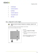
Страница 53: ...ine Connection Machine Configuration Installation_ Adjust X1 to X2 Angle Use this wizard to obtain correct angle between X axis and Y axis Typical use is after maintenance or repair Procedure 1 Execute the Adjust X1 to X2 Angle function 2 Follow the instructions exactly as given by the wizard Note Select a set of drilled vacuum holes 1 and 2 in the table top as reference 53 ...

Страница 54: ...tem Typical use is after maintenance or repair Procedure 1 Press the Adjust Measuring Station Position button 2 Follow the instruction given by the wizard 3 Repeat this procedure after maintenance on the Measuring Station 10 5 Set Ruler Position Machine Connection Machine Configuration Installation_ Set Ruler Position Follow instructions from the wizard If your table is equipped with Rulers please...

Страница 55: ...ce Point has been accidentially moved The Main Reference Point is a fixed position on the Cutting Table marked as a cross of drilled holes For more information go here 10 7 Map Table Top Surface Machine Connection Machine Configuration Installation_ Map Table Top Surface To assure correct Cutting Depth the surface of the Table Top is measured in order to create a map It is recommended to execute t...

Страница 56: ...make a perfectly compensated underlay for milling As this function is not used anymore and conveyor belts break the 5 mm limit iPC now always compensate based on table top mapping A registry setting is available to enable the old behavior 10 8 Calibrate Foot on Measuring Station Machine Connection Machine Configuration Installation_ Calibrate Measuring Pad Use this wizard to calibrate the height l...

Страница 57: ...fixed position on the Cutting Table marked as a cross of drilled holes The User Defined Reference Points are all specified relative to the Main Reference Point Thus moving the Main Reference Point will move these reference points as well The Main Reference Point has to be correctly positioned in order to obtain A full Work Area Correct Sheet Feed operation Correct handling of Long Jobs Using the M...

Страница 58: ...n a fixed position on the table Rx but not in the Main Reference Point R A special version of User Defined Reference Point is the Panel Reference Point 1 Position the Laser Pointer in the position where you want your Panel Reference Point 2 Press the Set Panel Reference Point button on Operators Panel The Panel Reference Point is set to current Laser Pointer Position 58 ...

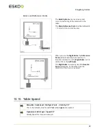
Страница 59: ...Reference Point will automatically be moved to an identical distance from the Right Ruler as it is defined from the Left Ruler The Right Ruler is normally used for Reverse Score operations At the same time the direction of the X axis is reversed 10 10 Table Speed Menu Bar Advanced Configure Tools Velocity X Y This is the default value for each Tool when Layers are created Opened Job Edit Layer Spe...

Страница 60: ...eleration for this particular Job 10 12 Jog Settings Continuous Jog speed The Continuous Jog Speed can be reduced to a value of the maximum jog speed Machine Connection Machine Configuration Setup_ Jog Speed Specify low and high Jog Speed Incremental Jog Step Size The size of the Incremental Jog movements can be customized Machine Connection Machine Configuration Setup_ Incremental Jog Specify Ste...

Страница 61: ...lculation The Table Top Reference function should be carried out After mechanical adjustments of traverse or tool head When cutting through material is not working properly After any change of cutting milling underlay for instance after adding or removing the milling underlay Procedure 1 Remove all materials from the table surface 2 Measure on top of the cutting underlay or conveyor belt 3 If the ...

Страница 62: ...setup is a one time job as long as the Vacuum Zone Solution on the machine remains unchanged The setup should correspond to the actual hardware The selected setup will determine which Vacuum Zone Configuration that will be available in the User Interface Machine Zone Configuration Vacuum Configuration C24 2 C44 2 62 ...

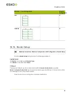
Страница 63: ...the following parameters Specify Router If a Router is mounded spedify Router Type If no Router is mounted select None COM port The physical COM port used for communication with the Router Control Unit is specified Note The Router Control Unit needs to be connected to a genuine COM port If connected to a USB to COM adapter the communication will fail These functions are used only after a hardware ...

Страница 64: ...ed Sheet in Load Position Sheet Load step 1 Sheet Load step 2 In some occasions the sheet unloaded from the cutting table can trigger the photo cell safety system To avoid this the sheet feed movement is divided into two steps 10 16 2 Sheet Feed Correction If the Conveyor Belt feed length needs adjustment use this function to adjust the movement of the Conveyor Belt to be shorter or longer 64 ...

Страница 65: ...10 Kongsberg C series 10 17 Board Size Not implemented yet 65 ...

Страница 66: ... for all tool settings and adjustments Select tool and function 11 1 Tool Configuration The C machine offers two different tool positions P1 and P2 where different interchangeable tools can be mounted In addition there are separate fixtures for Laser Pointer Measuring Foot Camera Drill and Pen Tools L Laser Pointer M Measuring Foot 66 ...

Страница 67: ...ease V notch Knife HD Knife Tool Yes FCU Foam Cutting Unit Yes HD Knife Tool Yes HPMU High Power Milling Unit Yes VibraCut Knife Tool Yes HF VibraCut Knife Tool Yes HiForce Knife Tool Yes RM Knife Tool Yes RotaCut Knife Tool Yes PressCut Yes Drill Pen Holder Drill Tool Ballpoint Pen Ink Tool Fibertip Tool 11 2 Tool Names Factory Tool Name The Tool Type mounted is identified by hardware codes insid...

Страница 68: ... Tool Machine Connection Configure Tools Adjust Selected Tool Follow instructions from the wizard From the Adjust Selected Tool dialog all Tool Adjustment Wizards are executed The following procedures are general descriptions of how to adjust the tools See the description of each Tool Type for more specific information We recommend using a sheet of Folding Carton material 5 6 mm 0 2 inch when exec...

Страница 69: ...e for all rotating tools Lag Test Machine Connection Configure Tools Adjust Selected Tool Lag Settings Lag Test Run this wizard to obtain correct Knife Lag value Follow the instructions in the dialog Add the measured value to the displayed value Circle Lag Circle quality is determined by a parameter called Circle Lag The parameter value will vary depending upon the actual material Therefore the ad...

Страница 70: ...Press the Adjust Active Tool button to enter the wizard selection dialog 3 Select Tool Height Calibration 4 Follow the instructions given by the wizard step by step 5 Repeat the procedure for all tools Typical use of this function is to add depth in order to ensure proper through cut in difficult materials 11 6 Rotation Adjustment for Rotating tools Optimal Angular Offset may vary with different m...

Страница 71: ...tate as the new value is activated 7 Press Tool Override Down and Jog approximate 10 cm to make a test cut 8 Press Tool Override Down once more to lift the Tool again 9 Press Tool Override Down once more to lower the Tool again 10 Note how the knife enters into the material 11 Press Tool Override Down once more to lift the Tool again 12 If knife enters exact into the cut the angle is correct selec...

Страница 72: ...figuration select one Tool 3 Press Adjust Active Tool to enter the Wizard Selection Dialog 4 Select Manual Adjustment of Center Offset and Angle 5 Enter value for the Center Offset and select Activate 6 Note that the Tool will move as the new value is activated 7 Press Tool Override Down and Jog approximate 10 cm to make a test cut 8 Press Tool Override Down once more to lift the Tool 9 Press the ...

Страница 73: ...ard step by step 11 9 Maintain Tool List Machine Connection Configure Tools More The More dialog contains selections to Ignore Delete or Add to the Tool List The Tool List contains Tools that you can select for the available Tool Positions Ignore Automatic Tool Identification Ignore Automatic Tool Identification may be used when the Automatic Tool Detection fails and manual tool selection is neces...

Страница 74: ...11 Kongsberg C series Add Tool Use Add Tool to Add new Tools Add tools that fails during Automatic Tool Detection The Tool is added to the Tool List 74 ...

Страница 75: ...explored General description How to operate How to adjust 12 2 Tool Handling and Care All Tools are precision instruments and should be treated as such to ensure proper operation Take special care when Tools are inserted or removed from their stations No excessive force should be applied Tools should not come in contact with hard surfaces while removed from their stations either temporarily or for...

Страница 76: ...e system by Tool Type In addition it is possible to identify up to four different tools of the same type One example If you have two different Static Knife Tools you can specify one to be number 1 and one to be number 2 In this way all Adjustment Parameters will be stored and recalled automatically as the tool is mounted onto the machine How to define individual Tool Numbers Inside each Tool there...

Страница 77: ...uipped with a Measuring Station The Measuring Station eliminates the manual adjustment of tool height The Measuring Station covers the following functions Calibrates the Measuring Foot Automatically measures the height of the tool tip If you for any reason would like to add an adjustment value to the measured value a height adjustment dialog is available from the Tool Configuration menu The Measur...

Страница 78: ...ng Station is working it is the tool tip that is measured Depending upon the actual tool it might be necessary to add depth in order to achieve cut or drill through the material Additional depth is entered in two ways The general depth of a Tool is entered from Machine Connection Configure Tools Adjust Selected Tool Tool Height Calibration The Job specific depth is entered from Opened Job Edit Lay...

Страница 79: ...mm Description A ø150 mm Crease Wheel mounted on an Heavy Duty Unit This Crease Wheel has the equivalent of 50 kg 110 lbs of down pressure The additional pressure combined with the large frontal area of the big wheel enables excellent crease quality in heavy duty Corrugated Board and even permits creasing board with high recycle content without breaking the liner A broad range of Crease Wheels wit...

Страница 80: ...upon the Blade Adapter Nominal value is 0 mm Tool Height Measured automatically possible to add an Offset Value Tool Rotation Adjust Tool Angle tangential to Moving Direction Center Offset Adjust Tool sideways until centered Tool Offset Adjust offset relative to Laser Pointer For more information about how to run the Adjustment Wizards see the Tool Configuration chapter 80 ...

Страница 81: ...rg C series 12 6 2 V notch Knife Tool Description The V notch Knife Tool mounted on a Heavy Duty Unit How to insert remove the V notch Knife Tool i 1 Turn the V notch Knife Tool correctly to fit the Guide Pin 81 ...

Страница 82: ...t is aligned with the Guide Pins c 4 Mount the new tool Note the position of the Guide Pin 5 Ensure that the tool height is calibrated on the Measuring Station About Tool Adjustment For the V notch Knife we recommend the manual procedures for Tool Rotation and Center Offset adjustment When adjusting Tool Rotation and Center Offset use a thin Folding Carton material Remember that you should look at...

Страница 83: ... Tool Offset Adjust offset relative to Laser Pointer For more information about how to run the Adjustment Wizards see the Tool Configuration chapter How to set the depth of the V notch Knife 1 The default depth of the V notch Knife is cut through the entire material 2 To make adjustment to the depth go to Opened Job Edit Layer 3 Normally the cut should extend down to just above the Bottom Liner Ho...

Страница 84: ...5 o 47 5 o V notch Knife Tool Modes of Operation Opened Job Layers Tab Edit Layer Menu Bar Layer Edit Layer Note V notch Knife Adapters are available for different knife angles 15 o 22 5 o 30 o 45 o 47 5 o In this chapter a 45 o knife angle is discussed The programming and operation will be similar for other angles Modes of Operation 84 ...

Страница 85: ...on to remove material from the middle of the cut Note This function is working along Y only Flute direction must be along Y The numbers indicates sequence of operation This illustration shows a typical use of Triple Cut Function The middle wall is not cut by 2 or 3 making the material impossible to fold The Triple Cut Function 1 cut the middle wall and you can fold the material nicely Geometry 85 ...

Страница 86: ...h to just above the bottom liner Adjust the cutting width W by the adjustment parameter dW Nominally the width of the cut has to be increased by dW 2 x bottom liner thickness dW limitations 20 mm dW 20 mm 0 8 in dW 0 8 in Decide if Triple Cut Function is needed This illustration shows how the parameter dW is used to ensure a nice folding result Triple Cut Function adjustment Adjustment sign and cu...

Страница 87: ...ife Tool is used for rigid board such as ReBoard and Triple Wall material The Tool is limited to Straight Lines longer than 50mm 2 The Tool is prepared for special trapezoid shaped Knife Blades How to replace a Knife Blade This picture shows how the Knife Blade is aligned against two Guide Pins 87 ...

Страница 88: ...ert remove the HD Knife Tool 1 Turn the HD Knife Tool correctly to fit the Guide Pin 2 Insert the two Latch Pins 3 Insert the Cotter Pins Tool Adjustments For this tool complete the following adjustments Adjustment Description Lag Setting The Knife Lag depends upon the Blade Adapter 88 ...

Страница 89: ...Direction Center Offset Adjust Tool sideways until centered Tool Offset Adjust offset relative to Laser Pointer For more information about how to run the Adjustment Wizards see the Tool Configuration chapter 12 6 4 Crease Adapter Using a Crease Adapter allows for smaller crease wheels used on HDU Adapters are available for ø15mm and ø26 mm crease wheels 12 6 5 Perforation Wheel ø60 mm 89 ...

Страница 90: ...ries Use Perforation Wheel to prepare perforation lines at high speed Suitable for corrugated board up to C flute 4 mm 0 16 in Perforation Wheel assembly Parts in assembly Ensure the path is clean Fix cover properly 90 ...

Страница 91: ... 0 mm Tool Height Measured automatically possible to add an Offset Value Tool Rotation Adjust Tool Angle tangential to Moving Direction Center Offset Adjust Tool sideways until centered Tool Offset Adjust offset relative to Laser Pointer For more information about how to run the Adjustment Wizards see the Tool Configuration chapter 12 6 6 Bevel Knife 45 Bevel Knife is a special purpose tool for 45...

Страница 92: ...the depth of the bevel cut in the Layer Setup Normally the cut should extend down to just above the bottom liner About tool adjustment For the Bevel Knife we recommend the manual procedures for tool rotation and centre offset adjustment Use a thin Folding Carton material when adjusting tool rotation and centre offset Remember that you should look at the bottom side of the material for correct alig...

Страница 93: ...the Tool Head is left on a table surface the Knife Blade might be exposed as the material hold down wheels moves up How to replace a Knife Blade Loosen the fixing screw replace the Knife Blade and fix it again No additional adjustments are necessary as the tool height is measured automatically A set of Knife Protection Handles are available Use them for safe knife handling 93 ...

Страница 94: ...le Use this function if 1 Your foam material is too soft for the measuring system 2 The surface of your material is un even When the Disable Material Thickness Measurement function is enabled the following rules applies Depth is referenced from bottom top of cutting underlay During Tool Up movements the knife is lifted to its top position Cutting Quality To obtain best quality when cutting details...

Страница 95: ...gential to Moving Direction Center Offset Adjust Tool sideways until centered Tool Offset Adjust offset relative to Laser Pointer For more information about how to run the Adjustment Wizards see the Tool Configuration chapter 12 8 HPMU High Power Milling Unit 12 8 1 Introduction Spindle motor Power rating max 3 kW Cooling system Liquid cooling Shank size max 8 mm RPM max 60000 Tool change Pneumati...

Страница 96: ...uck is described in detail in Chuck Change and Cleaning on page 110 This chapter is included just to remind you how important it is to use the Chuck Changing Tool available and a dummy bit to ensure correct mounting From left Chuck tool dummy bit with right diameter for the chuck and chuck Chuck change assembly Ready to be inserted into the spindle 96 ...

Страница 97: ...chip removal Adjust for proper operation 3 Air Clean Button to help remove contamination 4 Locking Screw for the suction house 5 Warning Lamp for spindle running 6 Chuck Open Close The shown position is closed Note To protect the chuck from damage and the spindle from contamination do not close the chuck over time without a dummy bit inserted Never start the spindle without a bit dummy bit in the ...

Страница 98: ...always insert a Dummy Bit when parking Lift HPMU in out of Park Position 1 Move the Y carriage to a position close to the gallows stand 2 Move HPMU to from HPMU Park Position as illustrated Chiller HPMU start up time Depending upon the environmental temperature the Chiller needs some start up time after Power On before it is ready to operate Typical delay is 2 3 minutes 98 ...

Страница 99: ... lock screw a 2 Adjust suction house to desired height Spindle RPM limitations Running 8 mm bits at a high RPM rate can generate vibrations and excessive wear Using Milling Bits with extended length at high RPM can also be dangerous Therefore using long Milling Bits is subject to an automatic RPM reduction If you are using short 8 mm bit these must be limited manually to 40 000 RPM In general 6 mm...

Страница 100: ...cted disconnected This is normal behaviour Maximum liquid dripping is specified to be 0 77 cm3 at each removal Use a rag of textile to avoid this liquid reaching material table top 12 8 4 Safety Issues Unattended Operation Depending upon the material processed milling introduce some risks It is a good rule to keep an eye on a milling job being executed Pay special attention to Do not leave the mac...

Страница 101: ...n indicated in red Suction House Always when executing a job let the Suction House float on top of the material In addition to chip removal the house reduces the risk of being hit by small work pieces or by a broken Router Bit Eye protection Use eye protection when working with HPMU Hearing protectors The noise generated by milling varies with the material being processed and running parameters Us...

Страница 102: ...pindle Power The HPMU spindle is prepared for continuous operation between 0 100 Watt A power load of 70 80 will allow good working conditions for the Spindle Motor Too high Spindle Power consumption indicates critical conditions for the motor and immediate actions should be taken 1 Use correct and sharp milling bit 2 Use correct RPM for the actual bit and material 3 Reduce the X Y speed If the mo...

Страница 103: ...ck Open Close valve operation Never operate the Chuck Open Close Valve while the Spindle is running This will destroy the Spindle Air Pressure and Quality Never run IBAG spindle with Pressurized Air disconnected This will destroy the Spindle Use Clean Air The Spindle is sensitive for the Pressurized Air quality Regularly check the Air Pressure Reduction Valve according to the Maintenance Descripti...

Страница 104: ...dures strictly Chuck Change and Clean Long Term Storage More than 4 weeks storage of a Spindle or a HPMU requires 1 Turn the unit upside down about 20 turns every 4 weeks 2 The Spindle must be stored horizontally Consider having a Replacement Spindle If HPMU is used in regular production it is recommended to have a Replacement Spindle The service interval will depend on the type of operation and i...

Страница 105: ...rew size Also check by hand that the Spindle rotates smooth without any resistance Empty Vacuum Cleaner in time 1 Do not leave the machine running if the Vacuum Cleaner can be over filled This might cause damage 2 Be aware the risk of suction tube clogging 12 8 6 Routing Advice Milling Bits For thin materials use bits with short cutting length 105 ...

Страница 106: ...r than shank diameter Bits with small cutting diameter 3 4 mm 0 12 0 16 in are more balanced than bits with larger cutting diameter Thus they can run with higher RPM normally 60 000 Use large diameter bits 5 6 mm 0 20 0 24 in when needed only Typical use is to get rid of the chips in thick materials Max RPM HPMU 60 000 Router Bit Edges are brittle Never let bits touch each other or other hard surf...

Страница 107: ...un much faster The surface finish or the Power Consumption will normally determine the final Feed Rate for an application A large drop in RPM or a high Watt value in the display indicate too high Feed Rate Large diameter bits require more power than small diameter bits Worn bits increase the Power Consumption Number of Passes in Thick Materials The Number of Passes depends on Material Type Milling...

Страница 108: ...mbining a heavy tool head with high quality cutting tools 12 8 7 Cleaner Device Cleaning the suction house is simple using a Cleaner Device which is available as an option 12 8 8 Bits and Bit Change How to insert replace a Router Bit 1 Ensure the Spindle is not running the lamp is dark Mind the sharp bit and move the Suction House up Lock the house in its up position 108 ...

Страница 109: ...ose lever down to open the Chuck Put the bit in a proper storage container Insert a new Router Bit Close the Chuck 3 Only the round part of the shaft should be inside the Chuck See the Bit Length and Position chapter for more information 4 Release the Lock to allow the Suction House moving down to its down position 109 ...

Страница 110: ...Valve or the Pressurized Air source If the bit is still stuck see the Chuck change and cleaning section about how to unscrew the chuck 12 8 9 Chuck Change and Cleaning Clean the taper and the chuck regularly for proper operation and optimum life time at least once a week but more often if necessary Follow the procedure strictly Normally the chuck has a long lifetime Extended vibrations or impacts ...

Страница 111: ...e chuck and remove any bit Note Never apply Compressed Air for cleaning 2 Apply the 17 mm key to hold the Spindle Rotor Note Do not turn the rotor when Chuck is in open position This might damage the Spindle 3 Enter the Chuck Tool with a Dummy Bit into the chuck 111 ...

Страница 112: ...nd unscrew the chuck using the Chuck Tool If the bit is stuck hold the rotor with the 17 mm key and unscrew with a 12 mm key Note Tool Open must be pressurized 5 Use the Taper Brush to clean the Taper 6 Push the Air Clean Button to help remove contamination 112 ...

Страница 113: ...e clamping force 8 Apply small quantities of grease to the threads of the chuck and to the outer cone and cylindric surface of the chuck green arrows Avoid the clamping area red arrow Do not use oil as it could enter the clamping area and reduce the clamping force 9 Torque up the chuck by hand using the Chuck Tool with a Dummy Bit Hold the rotor with the 17 mm key 10 Close the chuck on a Dummy Bit...

Страница 114: ...mediately if you experience any problems as 1 Bit slipping 2 Bit vibrations When replacing the chuck follow instructions in Chuck Change and Cleaning on page 110 New chucks are available from Esko store 12 8 11 Bit Length and Position Keep distance d small For best performance and minimum wear do not let the bit stick out more than necessary Use bits with short cutting lengths for thin materials 1...

Страница 115: ...s Adjustment Description Tool Height Measured automatically possible to add an Offset Value Tool Offset Adjust offset relative to Laser Pointer For more information about how to run the Adjustment Wizards see the Tool Configuration chapter Notes regarding Tool Height adjustment When properly adjusted the Router Bit should barely touch the top surface of the material 12 8 13 Table Top and Tool Heig...

Страница 116: ...08 inch above the cutting underlay Thus it is not possible to mill through the material in this case Tool Height will follow the mapped tabletop Milling Underlay U on top of the Cutting Underlay To be able to mill through the material the thickness of the Milling Underlay must be 2 mm 0 08 inch Tool Height will follow the mapped tabletop 12 8 14 Miscellaneous Warm Up Machine Panel Toolbar Warm Up ...

Страница 117: ... Cleaner can be used for automatic cleaning of the felt mat Prepare program to make a file that covers the actual area Set bit size to 65 mm 2 5 inch Hint Make a file name that reflect the size used Prepare Layer Setup with low spindle speed zero depth and maximum feed Insert the Dummy Bit into the chuck Adjust the brush height until the brush barely touches the mat surface 12 8 15 LubriCool Intro...

Страница 118: ...nspection window B Suction cup with nozzles LubriCool control unit How to use LubriCool is on when the Vacuum Cleaner is on For materials where lubrication is not suitable use the ON OFF switch on the LubriCool Control Unit to switch off lubrication 118 ...

Страница 119: ...s Inspection Opening When the LubriCool unit is on you can see light in the control relays inside the unit Oil For LubriCool use this oil only Accu Lube LB 5000 Use Nozzle Unit or Suction Ring Nozzle Unit Suction Ring 119 ...

Страница 120: ... the LubriCool function is beneficial only For all other materials especially MDF use the Suction Ring Note It is crucial for proper operation that these guidelines are followed How to interchange the Nozzle Unit Suction Ring Release locker A Replace Nozzle Unit Suction Ring Engage locker A Remove insert the Nozzle Unit oil tube from the outlet Nozzle Unit with oil tube Cleaning 120 ...

Страница 121: ...ion Release locker A and remove the nozzle unit Use vacuum cleaner to clean the HPMU suction house Use vacuum cleaner to clean the nozzle unit 12 9 Chiller no 1 for HPMU 12 9 1 Introduction This is chiller 1 replaced in October 2016 by a new model named chiller2016 121 ...

Страница 122: ...ns are still needed Press On Off button to start the heater The letters BCS are displayed To turn unit off push and hold the button for 3 seconds Media temperature is displayed Green light on the unit is on and the specified temperature is reached Green light flashing heating elements are operating Red light on fault condition over heating cable breakdown Program selection Press and hold the Menu ...

Страница 123: ... One common error signal is routed from the Chiller system to the inverter and further into the control system The following error conditions are monitored Temperature out of range high and low Liquid flow too low less than 0 5 l min The signal is 1 minute delayed Temperature sensor failure If any chiller failure occurs you have to look at the chiller display to see the real reason for the problem...

Страница 124: ...d More information is available from the Operating instructions for the chiller 12 10 Chiller2016 for HPMU 12 10 1 Introduction Specifications Dimensions W x D x H 480 x 580 x 430 mm 19 x 23 x 17 in Weight Empty 40 kg 88 lbs Filled with water 49 kg 108 lbs Internal heater This chiller is equipped with an internal automatic heater Chiller Unit 124 ...

Страница 125: ...19 o C 66 o F The chiller is equipped with an internal automatic heater First time startup Check that the supply matches the rated voltage Check that the electrical connection has been made correctly 12 10 3 Error Conditions One common error signal is routed from the Chiller system to the inverter and further into the control system The following error conditions are monitored Temperature out of r...

Страница 126: ...orrect water level in the Water Level Indicator on Chiller front H1 Temperature of cooling medium too high 35 o C 95 o F L1 Temperature of cooling medium too low 19 o C 66 o F Continue after error situation Find root cause for the error situation and fix it Flow too low is normally caused by a squeezed water hose Switch chiller unit OFF and ON again More information is available from the Operating...

Страница 127: ...braCut Running with 12000 RPM and amplitude 0 6 mm 0 024 inches this tool is recommended for more demanding Corrugated Materials Note Hearing Protection is recommended when working with this tool Common to both models To reduce material tear a foot is available The same set of Knife Adapters can be used Replace Knife Blade Pull straight out to remove the Knife Foot 127 ...

Страница 128: ...left Tool Adjustment For this tool complete the following adjustments Adjustment Description Lag Setting The Knife Lag depends upon the Blade Adapter Nominal value is 0 3 mm Tool Height Measured automatically possible to add an Offset Value Tool Rotation Adjust Tool Angle tangential to Moving Direction Center Offset Adjust Tool sideways until centered Tool Offset Adjust offset relative to Laser Po...

Страница 129: ...al Knife RM Knife Tool Replace Knife Blade Use a 3 mm Allen key to fix loosen the Knife Blade Ensure the Knife Blade is correctly aligned No additional adjustments are necessary as the tool height is measured automatically Tool Adjustment 129 ...

Страница 130: ... Tool Offset Adjust offset relative to Laser Pointer For more information about how to run the Adjustment Wizards see the Tool Configuration chapter 12 13 HiForce Knife HiForce Knife is a general purpose knife tool suitable for cutting a wide range of materials As the name indicates this tool is prepared for a higher tool pressure compared to the Static Knife The tool is prepared for a wide range ...

Страница 131: ...sition relative to the screw Push the Knife Blade down while the screw is fixed Extreme care should be taken when inserting the Knife Foot again Keep fingers away from Knife Blade as illustrated at left Tool Adjustment For this tool complete the following adjustments Adjustment Description Lag Setting The Knife Lag depends upon the Blade Adapter 131 ...

Страница 132: ...oving Direction Center Offset Adjust Tool sideways until centered Tool Offset Adjust offset relative to Laser Pointer For more information about how to run the Adjustment Wizards see the Tool Configuration chapter Replace Knife Adapter To remove the Knife Adapter just pull it out from the holder 12 14 Psaligraphy Knife Note iPC version 2 0 or higher is required to run this tool 132 ...

Страница 133: ...tremely careful when mounting the foot Tool Adjustment For this tool complete the following adjustments Adjustment Description Lag Setting The Knife Lag depends upon the Blade Adapter Nominal value is 0 3 mm Tool Height Measured automatically possible to add an Offset Value Tool Rotation Adjust Tool Angle tangential to Moving Direction Center Offset Adjust Tool sideways until centered Tool Offset ...

Страница 134: ...ward knife pressure The pressure is adjustable from Opened Job Edit Layer dialog For applications where a more accurate depth control is required a simple foot solution is available The tool is prepared for a wide range of Knife Blades Replace Knife Blade This figure shows how the Knife Blade is fixed inside the PressCut Knife Tool The friction between the Alignment Pin A and the Knife Blade keeps...

Страница 135: ... Tool Pressure In the dialog specify the Tool Pressure The pressure is entered as a gram value from 40 to 700 grams The Knife Pressure is modified if Speed Dependent Tool Pressure is specified see below During the tool down movement the knife moves down until the material surface is detected and the proper Knife Pressure is achieved The Knife Pressure needed will vary depending upon the material F...

Страница 136: ...e Knife Pressure parameter see previous chapter Curve B illustrates the Speed Dependent Tool Pressure Ramp Value is set to 100 When running at full speed the pressure is the double of the Knife Pressure A This function is useful as it allows a lower pressure in both ends of a line where the speed is low at the same time as you get a higher pressure when running at full speed Note The maximum Ramp ...

Страница 137: ...nt will increase the Cutting Depth 12 16 RotaCut RotaCut is a special tool for cutting light materials as thin fabric Maximum Cutting Depth is 2 mm 0 07 inch Note Due to the characteristics of this knife tool some restrictions apply to the use of it It is not suitable for curves with small diameter It is not suitable for designs containing short lines in combination with sharp angles 137 ...

Страница 138: ...25 mm 1 inch How to replace the Knife Blade 1 Use the spanner and the hexagonal screw driver to remove the Knife Blade fixing nut 2 Carefully remove the old Knife Blade and insert the new one Ensure the Knife Blade is properly seated Mount the nut and fix it properly 138 ...

Страница 139: ...ot movement is smooth Tool Adjustment RotaCut is adjusted in the same way as the other C tools regarding rotation angle and offset Tool Height is manually adjusted Tool Height for RotaCut is manually adjusted using the tool height adjustment wizard available from the Tool Configuration dialog Follow the instructions in the dialog Be careful though not to adjust the cutting depth too deep into the ...

Страница 140: ...inch Width 7 0 mm 0 28 inch Use the Lag and Width parameters to achieve proper corner cutting 12 17 Braille Tool Braille Tool will enable you to create signage readable by visually impaired people Braille Tool is prepared for use in combination with HPMU Braille Tool how to add spheres 140 ...

Страница 141: ...ghtly 5 Push the dispensing mechanism up 6 One sphere should be pushed out from the tool Plunger The tool is equipped with a plunger that serves two purposes 1 To force the spheres into the internal funnel 2 Indicate the number of spheres remaining in the tool If the groove is no longer visible it means that there is a limited number of spheres left in the tool Braille Tool milling bit 141 ...

Страница 142: ...nection Tool Configuration 1 Load the Braille Tool with black spheres 2 Cut a piece of double sided tape measuring approximately 20x20 mm 0 8x0 8 in and stick it to the surface of the working area Preferably the milling underlay or your selected substrate It is important that the piece of tape fits within the hole in the measuring foot with good margins 3 Insert the Braille Tool in the MultiCUT to...

Страница 143: ... on Preparing Layers for Braille Tool Opened Job Layers Edit Layers When making braille signage you need two identical Layers with the braille pattern one for milling holes and one for inserting braille spheres These Layers may consist of circles or points Layer Braille Drilling HPMU Velocity Z Velocity Z is material dependent and may require experimentation The value shown in the illustration is ...

Страница 144: ...termines the pressure the Braille Tool will use to force the sphere into the hole If you are using soft materials and notice indentations in the material you can lower the value to get a lighter pressure On the other hand if the spheres are not fully inserted into hard materials like acrylic you may increase this value to increase the force used by the Braille Tool Drill Holes Drill Holes check bo...

Страница 145: ...ndle as well as Braille spheres being inserted with the Braille Tool it is recommended to duplicate the Braille Layer Keep other graphics than Braille in separate layers 12 18 CorruSpeed Knife Note iPC version 2 0 or higher is required to run this tool CorruSpeed Knife tool is made especially for cutting corrugated materials Maximum material thickness 7 mm 0 28 in Maximum knife edge height 6 5 mm ...

Страница 146: ...ssure must be adapted to each material Run some test cuts to find the best combination of knife tip exposure and foot pressure Start with foot pressure 5 and test with different knife tip exposures By this you can find and save settings that are optimal for each type of material Note When adjusting the knife tip exposure do not adjust the knife tip too far into the foot The limit is when the knife...

Страница 147: ...tment For this tool complete the following adjustments Parameter Description Lag Setting The knife lag depends upon the blade shape Normal value is 0 mm Tool Height The tool tip should touch the material surface Tool Rotation Adjust tool angle tangential to moving direction Center Offset Adjust tool sideways until centered Tool Offset Adjust offset relative to Laser Pointer For more information ab...

Страница 148: ...red for use in combination with HPMU Braille Tool how to add spheres 1 Keep the tool in upright position during this process 2 Remove the cap and the plunger 3 Pour spheres into the tool 4 Insert the plunger and the cap Shake the tool lightly 5 Push the dispensing mechanism up 6 One sphere should be pushed out from the tool 148 ...

Страница 149: ...ot use this bit when warming up the milling spindle as the warm up sequence exceeds 20 000rpm Braille Tool setup In order to create high quality consistent braille patterns you should perform Tool Height and Tool Offset calibrations Before adjusting offset you should set the tool height of the Braille Tool This can be done manually or automatically using X Pad Note It is crucial that the Tool Heig...

Страница 150: ... is placed in the middle of the piece of tape 8 Press Start The machine will measure the material thickness and dispense a sphere onto the tape piece If the Laser Spot is offset from the sphere jog the tool head until the Laser Spot is placed exactly on top of the sphere 10 Click Finish and close the remaining tool adjustment dialogs Configure Tool Menu Bar Advanced Configure Tools Braille Tool sh...

Страница 151: ...res sit too low or too high The standard specifies a sphere height of 0 6mm 0 023 Example using 3mm Dibond 1 07mm 3mm 1 93mm Spindle RPM Spindle RPM is material dependent and may require experimentation The values shown in the illustration are suitable for 3mm Dibond Drill holes Drill holes check box should be enabled Layer Braille Tool Z axis Depth Z axis depth should initially be set to the mate...

Страница 152: ...blishing software To create the Braille patterns select the Braille font and type the text Select a font size which gives correct distance between the dots patterns Details are found in the Raster Braille manual As with other fonts outlines of the text need to be created before creating the output file for i cut Vision Since the Braille patterns should be drilled with the HPMU spindle as well as B...

Страница 153: ...ocked in position To remove a Tool press the Release Button Pen Drill Motor Connector To release grab the housing and lift straight up To insert move connector carefully down and turn it until it fits Then just push the connector down until it is locked in position 153 ...

Страница 154: ...he chuck Use the wrench to fix the bit in the chuck No additional adjustments are necessary as the tool height is measured automatically Tool Adjustment For this Tool complete the following adjustments Adjustment Description Tool Height Measured automatically possible to add an Offset Value Tool Offset Adjust offset relative to Laser Pointer For more information about how to run the Adjustment Wiz...

Страница 155: ...with spring and Pressure Adjustment Knob C pen tool Adjust Tool Pressure using the screw s Lock the adjustment screw using the locking knob k Tool Adjustment For this tool complete the following adjustments Adjustment Description Tool Height Measured automatically possible to add an offset value Center Offset Adjust tool sideways until centered Tool Offset Adjust offset relative to laser pointer F...

Страница 156: ...L in the illustration is a Class II laser beam Pointing Device Wavelength 650 nm 1 mW The Laser Pointer is used in adjustment wizards and job execution to indicate current position on the table The Laser Pointer is lit as long as it indicates the correct current position If there is no manual operation of the table the Laser Pointer will be switched off after a 30 sec time out Pressing any button ...

Страница 157: ...nt in order to prevent any irregularities Clean The Table Surface should be kept clean at all times For cleaning use iso propyl alcohol or white spirit The room should be cleaned regularly Keep the cables free from grease floor vax etc Use a Vacuum Cleaner to keep the inside of the Conveyor belt clean 13 3 Weekly Maintenance Guide ways and Bearings The guide ways and the bearings should be thoroug...

Страница 158: ...water in the glass bowl of the pressure reduction valve drains out automatically during the first few seconds of operation 3 Remove and clean the bowl if the automatic draining action does not operate or if it appears to be an excessive amount of dust in the bowl Warning If the automatic draining action fails water can enter the Tool Assembly resulting in severe damage 13 4 Monthly Maintenance Mon...

Страница 159: ... opened in order to retain the hold down efficiency Use a steel pin 0 5 0 6 mm With the Vacuum System switched on free the vacuum holes by pushing the obstructions down into the table 13 5 Maintenance External Equipment All external equipment as PC Vacuum pump and compressor should be maintained according to the User Manual for the actual equipment 159 ...

Страница 160: ...cedure Switch Power Off using the Main Power Switch Remove the Main Power plug from the wall socket Note Some of the equipment described here is optional 14 1 Mains fuses inside MPU MPU location Note MPU location is model dependent All fuses are located inside Main Power Unit MPU 160 ...

Страница 161: ...U 2 Pull out the MPU cabinet 3 Check if the actual fuse is blown is in OFF position 4 If blown turn the actual fuse switch to ON position as illustrated above 5 Replace base cover 6 Insert main power cable into the wall socket and turn main power on 14 2 MPU fuses MPU location 161 ...

Страница 162: ...he actual fuse is blown 4 If blown replace the actual fuse 5 Replace base cover 6 Insert main power cable into the wall socket and turn main power on Fuse details F24 1 T 6 25A 250V 6 3 x 32 mm F24 2 T 6 25A 250V 6 3 x 32 mm F48 T 8A 250V 6 3 x 32 mm F200 T 15A 250V 6 3 x 32 mm 14 3 X1 amplifier X1 amplifier location 162 ...

Страница 163: ...e cover from AC amplifier unit 3 Check fuses F2 F5 with ohm meter If blown replace with a new identical fuse 4 Replace covers 5 Insert main power cable into the wall socket and turn main power ON Fuse details T 10A 250V 5 X 20 mm 14 4 X2 amplifier X2 amplifier location 163 ...

Страница 164: ...ve cover from AC amplifier unit 3 Check fuses F2 F5 with ohm meter If blown replace with a new identical fuse 4 Replace covers 5 Insert main power cable into the wall socket and turn main power ON Fuse Details T 10A 250V 5 X 20 mm 14 5 Y amplifier Y amplifier location 164 ...

Страница 165: ...or 5 Status lamp 6 P1 Z1 motor Procedure 1 Remove Y cover 2 Remove cover from AC amplifier unit 3 Check fuses F2 F5 with ohm meter If blown replace with a new identical fuse 4 Replace covers 5 Insert main power cable into the wall socket and turn main power ON Fuse details T 10A 250V 5 X 20 mm 165 ...

Страница 166: ...1 and P2 are located inside the Y carriage Fuse location Procedure 1 Access is available through holes in the Y carriage cover 2 Use a thin screw driver to reset the actual circuit breaker P1 FZ1 P2 FZ2 3 Insert main power cable into the wall socket and turn main power ON 166 ...

Страница 167: ...ed above lift straight up 4 Check with ohm meter If blown replace with a new identical fuse 5 Insert main power cable into the wall socket and turn main power ON 6 For information about fuse sizes see table below Fuse Details Tool Head Function Fuse Fuse Size Fuse Type Drill Tool Drill Fhr 2 T 2A 125V NANO 42441618 Hiforce Knife Tool Tool Rotation Fhr 2 T 2A 125V NANO 42441618 HF VibraCut Knife To...

Страница 168: ...otaCut Knife RPM 2 T 2A 125V NANO 42441618 VariCut Knife Tool Tool Rotation Fhr 2 T 2A 125V NANO 42441618 VariCut Knife Tool Knife Depth Fu d 0 5 T 0 5A 125V NANO 42441600 VibraCut Knife Tool Tool Rotation Fhr 2 T 2A 125V NANO 42441618 VibraCut Knife Tool Vibration Fu d 2 T 2A 125V NANO 42441618 HDU XP Tool Rotation Fhr 4 T 4A 125V NANO 42444828 14 8 Chiller1 fuse Remove the on off button Remove c...

Страница 169: ... the fuse 1 Spare fuse 2 Fuse in action Fuse 115V T 2A 250V 5x20 mm 230V T 1A 250V 5x20 mm 14 9 Heater for Chiller Fuse Heater Fuse Location The Fuse is available inside the connector cover Fuse details F 4A 250V T 5x20mm Slow Blow 42448944 14 10 Chiller2016 Fuse replacement 169 ...

Страница 170: ...0V 5 X 20 mm 42468066 F3 T 500 mA 250V 5 X 20 mm 42468074 Fuses when 230 V F1 T 12A 250V 5 X 20 mm 42468082 F2 T 12A 250V 5 X 20 mm 42468082 F3 T 500 mA 250V 5 X 20 mm 42468074 14 11 TakeUp Unit Fuse replacement The fuses are mounted on the main electrical mounting plate behind the sheet metal cover on the right side of the machine Fuse F1 T10 A 250V 5x20mm 42448985 The same fuse size is used rega...

Страница 171: ...14 Kongsberg C series Fuse F2 T2 5 A 250V 5x20mm 44347540 The same fuse size is used regardless 115V 230V 171 ...

Страница 172: ...rnings Powerful magnets inside Keep away from mechanical wristwatches and other items damageable by magnetic fields Keep away from loose metallic items and other magnets Magnetic field Can be harmful to pacemaker wearers Pacemaker wearers stay back 30 cm 12 in 172 ...

Страница 173: ...15 Kongsberg C series 15 2 Roll Feeder Mount Push the roll feeder towards the fixtures The roll feeder is kept in place by means of a set of permanent magnets 15 3 Roll Feeder Use 173 ...

Страница 174: ...15 Kongsberg C series Release the roll feeder Press down the release knob Pull the roll feeder out from the fixture Adjust brake force To increase brake tension push the brake handle down 174 ...

Страница 175: ...rg C series To decrease brake tension pull the brake handle up Release roller bar Open the chuck to release the roller bar Close the chuck to lock the roller bar Note Never run the machine with the chuck open 175 ...

Страница 176: ...es 16 Collector Basket The unit is placed in the unload end of the conveyor belt front of table The unit is prepared for rigid pieces up till 200x200 mm 8x8 in or flexible materials Maximum load weight is 30 kg 65 lbs 176 ...

Страница 177: ...nd flawlessly as possible Read this manual carefully before starting the machine Familiarize yourself thoroughly with the functioning of the machine Strictly observe the directions given Liability The data published in this manual are based on the latest information available They are subject to future modification We reserve the right to change the construction and or design of our product withou...

Страница 178: ...u will find these pictograms near the text referring to the operations risks Work safely We have made everly effort to inform you as correctly and completely as possible on any dangers associated with the operation of the machine You must ensure and are responsible for compliance with these behavioural guidelines The buyer user is obliged to familiarize operating cleaning and maintenance personnel...

Страница 179: ...th a Autogrip shaft which is driven on the left side of the machine This autogrip shaft has a variable winding speed depending on the height of the dancer roller Machine Identification The TakeUp Unit has an identification label a typical label is shown in the picture The identification label is positioned on the left side of the machine where the power cable is entering the machine 17 3 Safety Ge...

Страница 180: ...s to make sure that the only people allowed to work with and on the machine have understood the basic rules on workplace safety and accident prevention The owner will make sure that the personnel is trained in the handling of the machine and have been familiarized with the operating and safety instructions contained within this manual The safety awareness of personnel shall be reviewed at regular ...

Страница 181: ...s at a complete stop and powered down Informal Safety Measures The user manual must be kept with the machine In addition to the operating instruction the local accident prevention regulations and environmental regulations should be available All safety instructions and warning pictograms must remain in legible condition Security Measures for Normal Operation Only operate the machine if all safety ...

Страница 182: ...flict never run Milling Unit when TakeUp Unit is mounted 17 4 Features and components Components overview A Emergency switch B Autogrip shaft C Dancer roller D Frame E Control panel D Waste handling kit 17 5 General operation Control positions 182 ...

Страница 183: ...ent controls are shown in picture A Jog forward backward The jog button turns the autogrip shaft slowly forwards or backwards To Jog the winding direction button has to be set in position 0 B Winding direction The winding direction button controls the winding direction of the TakeUp Unit C Winding speed The windig speed potentiometer controls the winding speed D Spare E Power button The power butt...

Страница 184: ...h underneath the waste handling kit to reach the Autogrip shaft Take the winding material underneath the dancer roller and paste it with tape in a straight line onto the coil See picture for the typical loop of the winding media Avoid angular tension in the media the media will start telescoping during the winding Note TakeUp Unit should be started only when material is in place Infeed loop Aligni...

Страница 185: ...cy stop is activated Attention The TakeUp Unit does not stop automaticly when the waste roll is full This has to be done manually by switching off the power button or by activating the emergency stop button 17 8 Using the Autogrip Shaft Put the core media roll central on the autogrip shaft which uses rubber blocking cords to grip with Rotate the core media roll to engage it with the autogrip shaft...

Страница 186: ...osition to ensure safe operation and avoid risks for the operator Locking ring in unlocked position Locking ring in locked position Exchange media rollers The media needs to be cut when the media roll has reached it s maximum diameter or when the roll has to be exchanged Before cutting the media the TakeUp Unit has to be always switched off The tip has to be stuck to the roll to prevent unwinding ...

Страница 187: ...ding till the dancer roller rises to the start position Resetting TakeUp Unit The dancer roller will move to its lowest position when a roll of material is completed The TakeUp Unit will shut off automatically when the dancer is longer then 4 seconds in the bottom position The full roller can now be replaced by a new empty core The TakeUp Unit can be restarted by switching the winding direction to...

Страница 188: ... when the boards are ready on the support table The i BF lifts and transfers media from a customer s pallet on the floor onto its own support table at the transfer point to the finisher The i BF Board Feeders increase productivity and reduce operator time when the Kongsberg tables are used for serial production The i BF feeds corrugated paper core boards and plastics quickly and accurately from pa...

Страница 189: ...llows DANGER This warning attracts attention to hazards for yourself or others It highlights personnel safety related information Strictly adhere to this information Failure to be cautious of this warning could result in serious injury to yourself or others CAUTION This warning attracts attention to hazards for yourself or others It highlights personnel safety related information Strictly adhere t...

Страница 190: ...rriage beam at the lower end of travel Never reach into this area Moving Parts This symbol indicates possible risk of pinching between two rollers or between rollers or moving belts and the frame Keep hands away of the moving parts at all times Pinch Hazard This symbol represents pinch hazards near rolling assemblies that could catch an extremity or pull in loose clothing Be aware of these roller ...

Страница 191: ...wered into a position where there is less than 100 mm clearance between the beam end and the gantry base Therefore never reach into this area with your hand or other body part as there is a danger of crushing Gantry Lower Base Top Cover Support Roller Rolling Nip Danger There is a small plastic roller on each side of the lower gantry These rollers act to support the lower gantry upper cover as the...

Страница 192: ... Service Engineer and deemed qualified to operate this machine Failure to comply with this mandate could result in personal injury electric shock or damage to the i BF Please make the operator manual available to all personnel operating the i BF and make it accessible to the production department for reference Use only genuine Infinite Motion Control Inc replacement parts and materials only Furthe...

Страница 193: ...and padlock according to standard Lock Out Tag Out procedures whenever servicing the i BF Keep the work area clean Cluttered and dirty work areas tool carts and workbenches invite accidents Do not leave any foreign objects on or around the i BF during operation or while not in use Moving parts hazards DANGER The i BF is an automatic machine and may begin moving without warning Be cautious of i BF ...

Страница 194: ...top Safety Circuit The i BF has an emergency stop safety circuit The emergency stop safety circuit must be reset or energized ON in order for the i BF to operate in any mode When the safety circuit is de energized the i BF is in a faulted or safe condition The blue lighted Fault Reset pushbutton will flash when the i BF is in a faulted condition A faulted condition may be the result of Emergency S...

Страница 195: ...chine or are interacting with the i BF in a non standard manner Safety Bumpers The i BF has 6 safety bumpers located on the moving gantry All of the safety bumpers are connected in series to a bumper safety relay Tapeswitch controller The bumper safety relay is part of the Emergency Stop Safety Circuit Pressing any of the safety bumpers will cause the i BF to immediately emergency stop Gantry Upri...

Страница 196: ...he carriage beam is in the upper position DANGER Never lean over the lowered carriage beam Suction Cup Arms Overload Safety Bumper A safety bumper is located under the moving carriage beam This bumper detects when a suction cup arms has pivoted upward indicating a mechanical jam or an unexpected object directly under the beam has been detected 18 6 i BF Overview Main Machine Components 196 ...

Страница 197: ...r sensor is a proximity switch that detects a target disk on the moving compensator The target disk moves up when the suction cup contacts the top board on the stack This is the method used to determine the height of the stack of boards and the top surface of the support table 6 Support Table The i BF picks the top board off of the stack and transfers the board onto the support table 7 Support Tab...

Страница 198: ... the left side of the electrical enclosure 18 7 Power On Off Controls Main Power Disconnect and Power On Off Controls Main Disconnect switch The picture shows the Main Disconnect switch in the 1 or ON position The Main Disconnect switch is located on the door of the electrical enclosure Switching to the 1 or ON position connects the high voltage input power to the i BF electrical system The discon...

Страница 199: ...trol power to be turned off The machine will not operate in any mode when control power is off 18 8 Operator Controls The operator controls are located on the controls pedestal The operator control functions are described below 1 Emergency Stop pushbuttons The Emergency Stop pushbutton is pressed inward to cause the i BF emergency stop safety circuit to be de energized causing the machine to be in...

Страница 200: ... according to the parameters set through the Touch Screen Manual Mode In Manual Mode the i BF will not respond to commands from the table Manual Mode is used to manually jog the i BF gantry and carriage beam using the Jog selector switch as enabled in the touch screen 3 Jog FWD UP REV DOWN The Jog selector switch can be used to Jog the gantry Forward or Reverse or the carriage beam Up or Down The ...

Страница 201: ...ed as indicated by the flashing blue light Pressing the Fault Reset button will cause the safety circuit to be reset providing there are no active machine faults The blue light will stop flashing when the i BF safety circuit is reset 6 Tapeswitch Bypass Pushbutton There may be occasions where a safety bumper is pressed and cannot be released due to a mechanical jam The safety system cannot be rese...

Страница 202: ...creen 7 2 Find Stack Once the machine is Homed or when a new stack is placed in the feeder it is advantageous to allow the feeder to determine the height of the stack Pressing the Find Stack button on the Main screen of the touch screen will cause the carriage beam to begin lowering in search of the top of the stack When the plunger sensor detects the top of the stack the stack height is recorded ...

Страница 203: ...enabled the gantry will make several up down oscillations as set in the shaker mode parameters on the touch screen The shaker mode is helpful during picking in separating some media types 9 The Carriage Beam moves upward with the board to the upper Home position 10 Once the Carriage Beam reaches the upper Home position the gantry moves the board forward toward the cutter The gantry stops at the Pl...

Страница 204: ...l Manual chapter Board Feeder Settings Screens Main Screen 1 Main Screen Message Window The main screen Message Window will display 1 Active Machine Faults 2 Messages related to the machine sequence 3 Active servo fault codes The servo fault text and fault codes are hidden when no servo faults are active 2 Find Stack button The Find Stack button is used to cause the carriage beam to move down to d...

Страница 205: ...am and gantry to return to Home position This feature is helpful when recovering from a faulted condition or quickly returning the gantry to Home position after loading a new pallet of boards or after jogging the machine 6 Move to Place button In Auto Mode the Move to Place button will cause the Gantry to move to the forward most position toward the cutter This feature is used to move the gantry f...

Страница 206: ...e jog features When enabled the round circle associated with the screen button will be green Switching back to Auto mode automatically cancels the enabled Jog Functions 18 11 Starting Up the i BF for Daily Operation The i BF can be powered OFF when not in use by pressing the red Power OFF pushbutton located on the door of the electrical enclosure and or by switching off the main power disconnect M...

Страница 207: ... home position The rectangular bar will turn green when the homing process is completed Find Stack Height Press the Find Stack button on the Main Screen The carriage will move slowly down until the suction cup with the plunger sensor detects the top of the board stack The height of the stack is recorded by the control system and the carriage beam returns to the Home position The i BF is now ready ...

Страница 208: ...ard past the allowable beam travel limit A Carriage Upper Over travel fault may indicate that the vertical drive is failing or the drive parameters are incorrectly set If this fault occurs while Homing the machine then it is possible that the Home sensor has failed or is not set correctly 5 Feeder Carriage Lower Over travel Fault A proximity sensor located under the far side gantry vertical guard ...

Страница 209: ... used to set a protective zone that prevent the forward suction cup arms from colliding with the forward stack guides the support table or the electrical enclosure beneath the support table See section 8 9 2 1 for more information A travel Limits Interference Fault will occur whenever the carriage and gantry are moved into the interference zone as set by the travel limits To remedy jog the carriag...

Страница 210: ...der Gantry Not In Pick Position Fault The gantry must be located in the pick position over the pallet stack before the carriage will move downward to pick a board A Gantry Not In Pick Position Fault will occur when the gantry is not in the pick position and a pick command is issued by the cutter or the Start pushbutton is pressed Remedy Return the gantry to home position by pressing the Return Hom...

Страница 211: ...cy stop circuit is de energized 2 F130 132 134 Problem with the servo encoder feedback Possible causes Break in the motor feedback cable The motor feedback cable is unplugged from the servo drive or at the servo motor Possible defective cable or servo motor encoder 3 F234 237 Controls enclosure temperature too high 4 F301 Servo motor overheated Check for increased motor load due to binding in the ...

Страница 212: ...18 Kongsberg C series Versatile works well with most materials Special version for corrugated materials Special version for rigid materials 18 14 Emergency Stop Solution 212 ...

Страница 213: ...rd Feeder can be off No Emergency Stop buttons on Board Feeder are activated When any Emergency Stop is activated Both Cutting Table and Board Feeder will perform an emergency stop Remove the root cause for the emergency situation Reset the Emergency Stop button activated Power up the system Press Safety Reset on Cutting Table Other safety issues on the Cutting Table The Cutting Table safety syste...

Страница 214: ...18 Kongsberg C series Ensure the faulty situation is removed Press Safety Reset on Board Feeder to continue 214 ...

Страница 215: ...eeding and stacker flexible and rigid materials and eliminates the repetitive steps normally performed by a machine operator freeing the operator to perform other duties The Feeder Stacker is fully integrated to the digital cutter thought Ethernet communications The Feeder lifts and transfers media from a customer s pallet on the floor onto its own support table at the transfer point to the finish...

Страница 216: ...l safety related information Strictly adhere to this information Failure to be cautious of this warning could result in serious injury to yourself or others CAUTION This warning attracts attention to hazards for yourself or others It highlights personnel safety related information Strictly adhere to this information Failure to be cautious of this warning could result in serious injury to yourself ...

Страница 217: ...ween two rollers or between rollers or moving belts and the frame Keep hands away of the moving parts at all times Pinch Hazard This symbol represents pinch hazards near rolling assemblies that could catch an extremity or pull in loose clothing Be aware of these roller assemblies Failure to be cautious of this symbol could result in serious injury to yourself or others Read the user manual first T...

Страница 218: ...ess of 100 mm between the carriage beam end plate and the gantry base However there may be unusual circumstances no pallet no plunger sensor where the carriage beam can be lowered into a position where there is less than 100 mm clearance between the beam end and the gantry base Therefore never reach into this area with your hand or other body part as there is a danger of crushing This danger exist...

Страница 219: ...result in damage of the machine 19 2 5 Rules for Safe Operation Training requirement Only properly trained personnel can perform various tasks on the Feeder Stacker system The number of tasks a person is allowed to perform is directly linked to the level of training that person has received Operators can Operate the Feeder Stacker system Perform the maintenance tasks listed in this manual CAUTION ...

Страница 220: ...he Feeder and Stacker and remove them prior to starting the system Also check for damaged parts such as guards and safety devices and switches Check for restrictions on moving parts breakage of parts electrical cable damage and any other condition that may affect operation Please notify your service consultant as soon as you discover a damaged part Have any damaged part replaced immediately upon d...

Страница 221: ...ays remove all chains jewelry ties or similar garments when operating or working on the machine Wear safety shoes Wear safety shoes when loading unloading heavy materials to and from the Feeder Stacker Keep all machine fixed covers in place at all times during operation The system has several mechanically fixed machine covers Never operate the system with any fixed cover removed from either the Fe...

Страница 222: ...ssing the blue Fault Reset pushbutton on the pedestal control station The Fault Reset pushbutton will stop flashing and turn off when the safety circuit is reset 19 3 2 Emergency Stop Push buttons The system has six Emergency Stop push buttons one located on the pedestal control station one on each side of the feeder gantry one on each side of the stacker gantry and one on the stacker electrical c...

Страница 223: ...afety Bumpers Safety bumpers are located on each side of the moving gantry uprights to detect obstacles in the forward or reverse direction of gantry motion Gantry Upper Frame Underside Safety Bumper The Upper Frame Underside Bumper is located underneath the gantry upper frame This bumper protects against objects in between the moving beam and the upper frame when the carriage beam is in the upper...

Страница 224: ...nents 5 1 1 Feeder Gantry The feeder gantry is the entire horizontal moving assembly The Carriage Beam moves vertically up and down within the Gantry 5 1 2 Feeder Carriage Beam The carriage beam is the vertical moving beam that carries the suction cup arms 5 1 3 Feeder Suction Cup Arms The suction cup arms are attached to the carriage beam and can be adjusted horizontally across the carriage beam ...

Страница 225: ...ble materials onto the support table The roller is also used when the Esko roll unit is in service The roll material rolls over the support table roller over the support table and onto the cutter conveyor 5 1 8 Feeder Electrical Enclosure The electrical enclosure houses all of the electrical power and control devices The Main Power disconnect and Power On Off push buttons are located on the door o...

Страница 226: ...tack 5 2 4 Gantry Safety Bumpers The stacker gantry has four safety bumpers on the gantry vertical uprights one on each side of the two vertical uprights 5 2 5 Gantry Estop Push buttons An Estop push button is located on each side of the moving gantry 5 3 Stacker Utility Connections The stacker is supplied with a main power cord The power cord is connected to the stacker electrical controls consol...

Страница 227: ...enclosure door is allowed to open WARNING Never operate the i BF with the electrical enclosure door open and the disconnect manually switched to the ON position High voltage is also present within the enclosure even with the disconnect in the OFF position The i BF electrical system should only be serviced by qualified experienced technicians Power ON OFF Pushbuttons The Power ON OFF pushbuttons ar...

Страница 228: ...p safety circuit is de energized Once pressed the Emergency Stop pushbutton is maintained in the inward position The button is reset to the outward position by twisting in a clockwise rotation as indicated by the arrows on the button 2 Mode Manual Auto Selector Switch The Mode selector switch is used to put the system into Auto or Manual mode of operation Auto Mode In Auto Mode the system will res...

Страница 229: ... function must also be enabled on the touch screen On the touch screen enable the axis to be jogged 4 Start Pushbutton The Start pushbutton is active when the Mode selector switch is set to the Auto position When the feeder gantry is in position over the pallet pressing the Start pushbutton will cause the feeder to pick a board and deliver the board to the table When Hold at Place Position is enab...

Страница 230: ...on There may be occasions where a safety bumper is pressed and cannot be released due to a mechanical jam The safety system cannot be reset when a safety bumper is pressed The Tapeswitch Bypass pushbutton allows the safety bumper system to be bypassed to allow either the feeder or stacker to be jogged out of the mechanical jam situation The Tapeswitch bypass feature is only operational while a saf...

Страница 231: ...Pressing the Find Stack button on the Main screen of the touch screen will cause the carriage beam to begin lowering in search of the top of the stack When the plunger sensor detects the top of the stack the stack height is recorded and the carriage beam returns to Home position 3 i BF Sequence of Operation 1 Pick Command a Table communicates Pick Sheet to the Feeder or b The green Start pushbutto...

Страница 232: ... with the board to the upper Home position 10 Once the Carriage Beam reaches the upper Home position the gantry moves the board forward toward the cutter The gantry stops at the Place Position Location 11 See Low Advance to Cutter Option and Double Pick Options for other methods to place the board to the cutter conveyor 12 The Carriage Beam lowers the board to the Support Table The leading edge of...

Страница 233: ...er Main Screen 1 Main Screen Message Window The main screen Message Window will display 1 Active Machine Faults 2 Messages related to the machine sequence 3 Active servo fault codes The servo fault text and fault codes are hidden when no servo faults are active 2 Find Stack button The Find Stack button is used to cause the carriage beam to move down to determine the height of the stack The control...

Страница 234: ...urn to Home position over the pallet This feature is helpful when recovering from a faulted condition or quickly returning the gantry to the pallet position after loading a new pallet of boards or after jogging the machine 6 Move to Table button In Auto Mode the Move to Table button will cause the Gantry to move to the forward most position toward the cutter This feature is used to move the gantry...

Страница 235: ...trol screens are very similar in layout and function to the Feeder control screens 19 8 2 Jog Functions Screen The Jog Functions screen allows the operator to enable jogging of the vertical carriage beam UP Down and the horizontal Gantry Forward Reverse using the Jog selector switch on the control console The Machine Mode selector switch must be set to Manual in order to enable the jog features Wh...

Страница 236: ...so that all of the suction cups make contact with the top board 2 Delay to Build Vacuum Time The Build Vacuum time is that amount of time that the suction cups are in contact with the board to allow vacuum to develop before the carriage begins to lift the board The delay time is entered in seconds 3 Sheet Release Air Time When the board is released to the support table air is momentarily injected ...

Страница 237: ...Pause Position If the actual vacuum level is less than the Low Vacuum Set Point a Fail To Pick Board fault will occur To set the Low Vacuum Set point determine the vacuum level when no boards are in contact with the suction cups Set the Low Vacuum set point to the actual vacuum level 20 An easy way to determine the actual vacuum level with no boards in contact with the suction cups is to press the...

Страница 238: ...ne speeds Pressing one of the blue buttons will select the machine speed The associated round circle will turn green for the selected speed 19 8 7 Place to Cutter Method The feeder transfers the boards to the cutter to a position where the leading edge of the board is approximately 150mm onto the cutter conveyor When none of the Place to Cutter method options are selected the board is lowered dire...

Страница 239: ...d method for transferring boards to the cutter conveyor 2 Hold at Place Position After placing the board onto the cutter conveyor the feeder typically releases the board and returns to home position When enabled the Hold at Place Position feature causes the suction cups to remain on the board after the board is placed onto the cutter conveyor The suction cups raise off of the board and the gantry ...

Страница 240: ...ese screens are not protected and you should only access these screens if you are sure of the parameter changes that you wish to adjust or the features you wish to access Miss setting certain parameters can potentially cause machine damage Force Functions The Force Functions screen allows you to manually turn ON valves on the i BF This is useful when troubleshooting the feeder air valves The Mode ...

Страница 241: ... the front suction cups Back Release Air Air is injected into the carriage beam to neutralize the beam vacuum when the board is released to the support table Pressing the Back Release Air button will cause compressed air to be applied to the back suction cups Vacuum Generator Air The vacuum generator air valve is turned ON to supply compressed air to the vacuum generator The vacuum generator uses ...

Страница 242: ...button on the screen will bring up a key pad which allows you to enter the Place Position value Set the place position value to the current Horizontal position when the board is 150mm overlapping onto the cutter conveyor After setting the Place Position return to the Main Screen and press Vacuum Off and return the board to the stack Then press Return to Pallet on the Main screen Actual Horizontal ...

Страница 243: ...to the cutter The Low Advance to Cutter method causes the board to be lowered to the support table with the leading edge of the board short of the cutter conveyor The board lowers until the plunger sensor detects the support table When the support table is detected the carriage beam will raise the board to a low preset position and will advance the board in this low position onto the cutter convey...

Страница 244: ...puts The Monitor Outputs screen allows you to see the electrical state of all of the outputs from the feeder controller The round light next to the output name will be green when the output is energized ON and white when the output is OFF This screen can be useful when troubleshooting the feeder Engineering Protected Settings The Engineering Parameters are password protected and can only be access...

Страница 245: ...with the forward stack guides the support table or the electrical enclosure beneath the support table Fixed Horizontal Forward Place Travel Limit Sets the maximum allowable forward horizontal gantry position The travel limit is set to a position where the suction cup arms do not collide with the cutter beam and the board is placed 150mm onto the cutting table Machine Speeds Warning do not change a...

Страница 246: ...ain screen 9 2 Stacker Find Stack Once the machine is Homed or whenever a new pallet is placed into the stacker it is advantageous to allow the stacker to determine the height of the stack Pressing the Find Stack button on the Stacker Main screen will cause the carriage beam to begin lowering in search of the top of the stack When the plunger sensor detects the top of the stack the stack height is...

Страница 247: ...s when the upper plunger sensor detects the stack 10 The cut board is released to the pallet stack and the carriage returns to the full up position 11 The gantry then moves forward to the Park Position and waits for the next Pick command from the cutter 19 10 Touch Screen Display for Stacker Operation The Touch Screen display is used to interface to both the feeder and the stacker and allows acces...

Страница 248: ...e Home box will be Green once the machine has been homed 10 1 4 Vacuum Off button The vacuum to the plenums is turned ON when a board is being picked up off of the cutter conveyor and transferred to the pallet stack To avoid dropping a board the vacuum will remain ON when a machine fault occurs during the transfer sequence Pressing the Vacuum Off button will cause the vacuum to be turned OFF 10 1 ...

Страница 249: ... screens The Feeder control screens are very similar in layout and function to the Stacker control screens 19 10 2 Jog Functions Screen The Jog Functions screen allows the operator to enable jogging of the vertical carriage beam UP Down and the horizontal Gantry Forward Reverse using the Jog selector switch on the control console The machine Mode selector switch must be set to Manual in to enable ...

Страница 250: ...circuit The safety circuit will reset provided there are no active machine faults Homing the Feeder The feeder must be Homed before it will operate in Auto mode 1 Set the Mode selector switch to Auto 2 Press the Home button on the Main Screen The carriage beam will move up to the carriage home position and the gantry will move back to the gantry home position The rectangular bar will turn green wh...

Страница 251: ...plenum with the plunger sensor detects the top board on the stack The height of the stack is recorded by the control system and the carriage beam returns to the upper position The stacker is now ready for automatic operation with the cutter 19 12 Machine Faults Errors and Remedies The system is in a faulted condition whenever the blue Fault Reset pushbutton is flashing A faulted condition indicate...

Страница 252: ...ossible that the Home sensor has failed or is not set correctly 5 Feeder Carriage Lower Over travel Fault A proximity sensor located under the far side gantry vertical guard is used to detect if the carriage beam moves too low past the allowable beam travel limit A Carriage Lower Over travel fault may indicate that the vertical drive is failing or the drive parameters are incorrectly set 6 Feeder ...

Страница 253: ...ection 8 9 2 1 for more information A travel Limits Interference Fault will occur whenever the carriage and gantry are moved into the interference zone as set by the travel limits To remedy jog the carriage and gantry out of the interference zone 11 Feeder Plunger Sensor Stuck Fault The proximity sensor mounted on the first suction cup compensator is called the plunger sensor The plunger sensor is...

Страница 254: ...sition over the pallet stack before the carriage will move downward to pick a board A Gantry Not In Pick Position Fault will occur when the gantry is not in the pick position and a pick command is issued by the cutter or the Start pushbutton is pressed Remedy Return the gantry to home position by pressing the Return Home button on the main screen 15 Estop Not Energized Fault This is an indication ...

Страница 255: ... F130 132 134 Problem with the servo encoder feedback Possible causes Break in the motor feedback cable The motor feedback cable is unplugged from the servo drive or at the servo motor Possible defective cable or servo motor encoder 3 F234 237 Controls enclosure temperature too high 4 F301 Servo motor overheated Check for increased motor load due to binding in the conveyor system 5 F502 Bus under ...

Страница 256: ...19 Kongsberg C series Special version for corrugated materials Special version for rigid materials 19 14 Emergency Stop Solution The Cutting Table is equipped with 3 Emergency Stop buttons 256 ...

Страница 257: ...ted When any Emergency Stop is activated Both Cutting Table and Board Feeder will perform an emergency stop Remove the root cause for the emergency situation Reset the Emergency Stop button activated Power up the system Press Safety Reset on Cutting Table Other safety issues on the Cutting Table The Cutting Table safety system will be triggered Ensure the faulty situation is removed Press Safety R...

Страница 258: ...ter Shaking is important in order to maintain a good Vacuum Cleaner performance Filter Shaking is best operated every time before use and after prolonged operation Note This operation must be performed only when the Vacuum Cleaner is switched off and the motor has stopped Remove Material Container 1 258 ...

Страница 259: ...tainer with or without Plastic Bag Use Plastic Bag in Material Container Parts needed Steel ring and plastic bag Fix the Plastic Bag to the ring in this way Ring and Plastic Bag ready for the container Fold fix the Plastic Bag around the container 259 ...

Страница 260: ...ators and maintenance manual 20 2 Vacuum Cleaner High capacity TB ESKO 20 2 1 How to use Introduction 1 Filter Chamber 2 Filter Shaking Lever 3 Removable Material Container Note Carefully observe the Vacuum Cleaner filling level If the Vacuum Cleaner container is filled up completely the dust removal function will stop with a high risk for Spindle Motor damage 260 ...

Страница 261: ...Cleaner performance Filter Shaking is best operated every time before use and after prolonged operation Note This operation must be performed only when the Vacuum Cleaner is switched off and the motor has stopped Remove Material Container Note You can use the container with or without Plastic Bag 261 ...

Страница 262: ...he container Fix the Plastic Bag to the steel bar Plastic Bag with bar ready for container Fold fix the Plastic Bag around the container Container with Plastic Bag ready for operation Detailed information about how to operate the Vacuum Cleaner is available in the Operators and maintenance manual 262 ...

Страница 263: ...on tube inlet 2 Container fixture 3 Filter unit locking mechanism 4 Motor 5 Filter unit How to empty container 1 Ensure vacuum cleaner motor is off 2 Remove the suction tube 1 3 Release the container 3 4 Remove the filter unit 5 You should have a bucket nearby for the unit 263 ...

Страница 264: ...20 Kongsberg C series 5 Lift and turn the container to release it from the fixture 6 Empty the container 264 ...


Страница 265: ...21 Kongsberg C series 21 Install Software For information about software installation see the Installation Manual for the actual machine Available on the Documentation DVD 265 ...

Страница 266: ...ransmitters pointing correctly to their receiver Check if the red light is shining on the receiver If necessary adjust by bending the transmitter receiver holder During start up X1 X2 Y servo error This is probably caused by a defect in an amplifier board Please contact Esko for technical support During start up X1 X2 Y fuse error Check the fuse of the motor If problem persists it is likely to be ...

Страница 267: ...spindle Is the big green cable still well connected Check all connections of the milling spindle at tool head inside cover X1 and at the inverter Check serial connection between inverter and PC connection OK COM port changed lately If problem still persists contact Esko 2 or 3 tools are working at the same time Check your compressed air make sure you have 7 bar Check compressed air connection at t...

Страница 268: ... C series If there was a software update recently check if the firmware on the machine and iPC are of the same version Check the serial connection between PC and MCU Check the connection at the emergency button 268 ...

Отзывы: