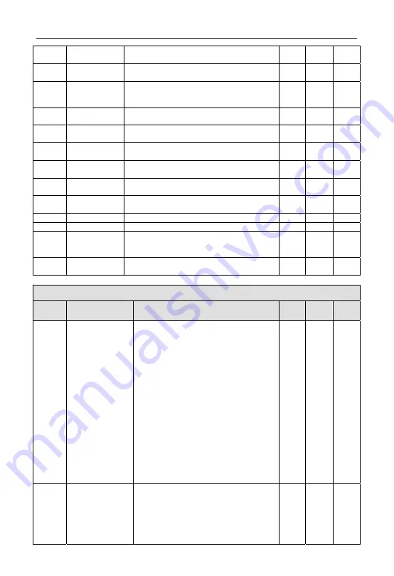
Function parameter schedule graph
40
flux current)
20
~
25: Reserved
F09.36 Analog
output(AO2)
selection
Same as above
1
0
○
F09.37 DO
function
selection (with Y4
reuse)
Same as above
1
0
○
F09.39 Analog
output
(AO1) filter time
0.0
~
20.0s 0.1s
0.0s
○
F09.40 Analog
output
(AO1) gain
0.00
~
2.00 0.01
1.00
○
F09.41 Analog
output
(AO1) bias
0.0
~
100.0% 0.1%
0.0%
○
F09.42 Analog
output
(AO2) filter time
0.0
~
20.0s 0.1s
0.0s
○
F09.43 Analog
output
(AO2) gain
0.00
~
2.00 0.01
1.00
○
F09.44 Analog
output
(AO2) bias
0.0
~
100.0% (AO2 output terminal with Y3 Reuse)
0.1%
0.0%
○
F09.45 DO
filter
time
0.0
~
20.0s 0.1s
0.0s
○
F09.46 DO output gain
0.00
~
2.00 0.01
1.00
○
F09.47 DO
maximum
pulse output
frequency
0.1
~
20.0KHz 0.1KHz 10.0KHz
○
F09.48 Torque reaches to
the detection time
0.02
~
200.00s 0.01s
1.00s
○
F10
-
Simple PLC/Multi-speed Function Parameter Group
Function
code
Name
Set range
Min.
unit
Factory
default
Modifi
-cation
F10.00 Simple
PLC
operate
setting
Units digit: Run mode selection
0: Inaction
1: Stop after single cycle
2: Final value keep after single cycle
3: Continuous cycle
Tens digit: Interrupt run restart mode selection
0: Restart from first phase
1: Continuous run from phase frequency at
interruption
2: Continuous run from run frequency at
interruption
Hundreds digit: PLC run time unit
0: Second
1: Minute
Thousands digit: Power-down memory selection
0: No memory
1: Phase of reserve power down, frequency power
down recording PLC run status: contain power
down phase, run frequency, time have run.
1 0000
×
F10.01 Step 1 setting
000H
~
E22H
Units digit: frequency setup
0: Multi-section frequency i (i=1
~
15)
1:Frequency determined by complex frequency of
main and auxiliary
2: Reserved
Tens digit: The selection of running direction for
1 020
○
ENC


