46
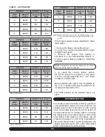
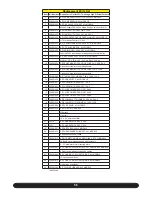
95V060-3
ESP 0.1” to 1.0” w.c.
HEAT
Jumper
ADJUST
Jumper
Low-Fire
CFM
High-Fire
CFM
A
NORM
700
1050
B
NORM
850
1105
C
NORM
575
880
D
NORM
525
819
95V080-3
ESP 0.1” to 1.0” w.c.
HEAT
Jumper
ADJUST
Jumper
Low-Fire
CFM
High-Fire
CFM
A
NORM
1050
1376
B
NORM
1250
1400*
C
NORM
900
1242
D
NORM
780
1108
* Motor CFM maxium
95V080-4
ESP 0.1” to 1.0” w.c.
HEAT
Jumper
ADJUST
Jumper
Low-Fire
CFM
High-Fire
CFM
A
NORM
1000
1350
B
NORM
1150
1495
C
NORM
900
1206
D
NORM
800
1104
95V100-5
ESP 0.1” to 1.0” w.c.
HEAT
Jumper
ADJUST
Jumper
Low-Fire
CFM
High-Fire
CFM
A
NORM
1200
1620
B
NORM
1400
1820
C
NORM
1100
1474
D
NORM
950
1349
Note:
Moving the ADJUST jumper from the NORM position to the
(+) or (-) position will increase or lower the temperature rise
by 15%
95V120-5
ESP 0.1” to 1.0” w.c.
HEAT
Jumper
ADJUST
Jumper
Low-Fire
CFM
High-Fire
CFM
A
NORM
1650
2200*
B
NORM
1900
2200*
C
NORM
1500
2070
D
NORM
1325
1815
* Motor CFM maxium
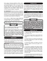
If the blower speeds require adjustment, follow
these steps:
1. Remove the blower compartment door.
2. Locate the 4 position movable HEAT jumper
to adjust heat speed.
3. Remove the jumper from position A
and place it on the corresponding letter B, C,
or D as required. Refer to TABLE 2 - HEATING
SPEEDS.
NOTE:
Temperature rise should always be re-checked
whenever blower speed is changed.
4. To adjust the cooling airflow, remove
the COOL jumper from position A and place
it on the corrosponding letter B, C, or D. Refer
to TABLE 10 AIR FLOW.
Moving the ADJUST jumper from the NORM to
the (+) or (-) position will cause the airflow to be
increased or lowered by 15%.
The TEST position on the ADJUST tap is not
used.
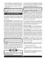
DEHUMIDIFICATION:
For situations where humidity control is a problem,
a dehumidification feature has been built into the
variable speed motor. At the start of each cooling
cycle, the variable speed motor will run at 82% of
the rated airflow for 7.5 minutes. After 7.5 minutes
has elapsed, the motor will increase to 100% of the
rated airflow. If this feature is not desired, clip the
jumper wire between Y and O on the integrated fur-
nace control board. With Y and O not jumpered, the
variable speed will reach 100% of the rated airflow
within 10 seconds of a call for cooling.
TABLE 3 - HEATING CFM
Содержание G95V
Страница 27: ...27 FIGURE 21A DIRECT VENT TERMINAL CLEARANCES...
Страница 28: ...28 FIGURE 21B NON DIRECT VENT TERMINAL CLEARANCES...
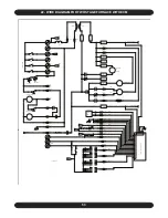
Страница 53: ...53 22 WIRE DIAGRAM FOR TWO STAGE FURNACE WITH ECM...

