40
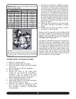
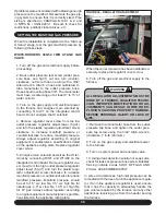
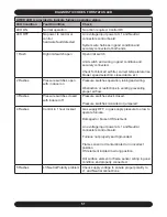
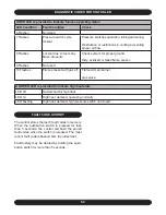
FIGURE 36 - INTEGRATED HOT SURFACE
INGITION CONTROL
!
!
!
!
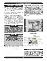
ELECTRICAL WIRING & CONNECTIONS
Before proceeding with the electrical connections,
ensure that the available electrical supply is com-
patible with the voltage, frequency and phase listed
on the appliance rating plate.
All furnaces are rated 120 vac, 60 Hz, 1 Ø. The
amperage rating is 15 amps or less.
Each furnace requires a dedicated 20 amp over-
current device, either a 20 amp circuit breaker or
a 20 amp Type D time delay fuse. It is permissible
to connect furnace accessories such as humidifier
transformers, condensate pumps and electronic air
cleaners. If adding accessory equipment to the fur-
nace circuit, ensure that the combined amperages
listed on the appliance rating plates does not ex-
ceed the rating of the over-current device.
WARNING
SHUT OFF ELECTRICAL POWER AT THE
FUSE BOX OR SERVICE PANEL BEFORE
MAKING ANY ELECTRICAL CONNECTIONS.
FAILURE TO DO SO CAN CAUSE ELECTRI-
CAL SHOCK RESULTING IN PERSONAL IN-
JURY OR LOSS OF LIFE.
WARNING
THE FURNACE CABINET MUST HAVE AN
UNINTERRUPTED GROUND.
A GROUND WIRE IS PROVIDED IN THE
ELECTRICAL JUNCTION BOX.
DO NOT USE GAS PIPING AS A
GROUND.
FAILING TO GROUND THE FURNACE PROP-
ERLY CAN RESULT IN ELECTRIC SHOCK RE-
SULTING IN PERSONAL INJURY OR DEATH.
In Canada, all electrical work must be in accor-
dance with the latest edition of CSA-C22.1, Cana-
dian Electrical Code Part 1, and any applicable lo-
cal code.
In the United States, all electrical work must be in
accordance with the latest edition of the National
Electrical Code, ANSI / NFPA 70.
•
•
•
16 - ELECTRICAL SPECIFICATIONS
Although a suitably located circuit may serve as
a service switch, a separate service switch is rec-
ommended. A separate service switch is necessary
if the circuit breaker is in a location where access-
ing it would require getting close to the furnace, or
if the furnace is located between the main electri-
cal panel and the entry to the furnace room. The
furnace switch (service switch) should be clearly
labeled, and installed in a location where it is not
likely to be mistaken as being a light switch or
similar control.
120V FURNACE CONNECTION
The furnace is shipped fully wired except for the
connections to the house wiring. The furnace pow-
er connections are made in a junction box inside
the blower compartment. The junction box is fac-
tory installed on the left hand side; however, it may
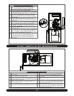
FIGURE 35 - ELECTRICAL CONNECTIONS /
MOLEX CONNECTOR
Содержание G95V
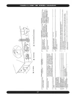
Страница 27: ...27 FIGURE 21A DIRECT VENT TERMINAL CLEARANCES...
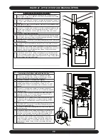
Страница 28: ...28 FIGURE 21B NON DIRECT VENT TERMINAL CLEARANCES...
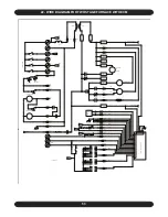
Страница 53: ...53 22 WIRE DIAGRAM FOR TWO STAGE FURNACE WITH ECM...

