47
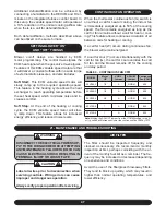
Additional dehumidification can be achieved by
connecting a humidistat to the DEHUM and R ter-
minals on the integrated furnace control board. In
this setup, the variable speed motor will operate at
a 10% reduction in the normal cooling airflow rate
when there is a call for dehumidification.
Both dehumidification methods described above
can be utilized on the same furnace.
SETTING BLOWER “ON”
AND “OFF” TIMINGS
Blower on/off delays are handled by ECM
motor programming. The control de-energizes the
ECM heat signal when the gas valve de-energizes.
Features of this ECM variable speed motor are that
it will deliver a constant airflow within a wide range
of external static pressures, and also includes:
Soft Start:
This ECM variable speed motor will
slowly ramp up to the required operating speed.
This feature in the heating cycle allows the heat
exchanger to reach operating temperature before
the set heat speed, which minimizes noise and in-
creases comfort.
Soft Stop:
At the end of the heating or cooling
cycle, the ECM variable speed motor will slow-
ly ramp down. This feature allows for increased
energy efficiency, and reduced noise levels.
!
!
!
!
21 - MAINTENANCE AND TROUBLESHOOTING
CONTINUOUS FAN OPERATION
When the thermostat continuous fan (G) switch is
on without a call for heat or cooling, the indoor fan
is immediately energized up to 50% of the cooling
speed. The fan remains energized as long as the
call for fan remains without a call for heat or cool-
ing. This feature allows continuous circulation of air
between calls for heating or cooling.
If a call for heat (W) occurs during continuous fan,
the blower will remain energized.
If a call for cool (Y) occurs simultaneously with the
call for fan (G), the call for cool overrides the call
for fan and the blower remains off for the cooling
on delay period.
WARNING
DISCONNECT THE ELECTRICAL POWER SUP-
PLY TO THE FURNACE BEFORE ATTEMPTING
ANY MAINTENANCE. FAILURE TO DO SO CAN
CAUSE ELECTRICAL SHOCK RESULTING IN
PERSONAL INJURY OR LOSS OF LIFE.
CAUTION
Label all wires prior to disconnection when
servicing controls. Wiring errors can cause
improper and dangerous operation.
Always verify proper operation after servicing.
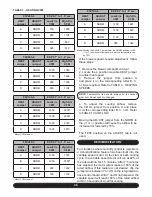
TABLE 4 - CONTINUOUS FAN CFM
MODEL
Motor
HP
COOL
Jumper
ADJUST
Jumper
Continuous
Fan (CFM)
95V060-3
1/2
A
NORM
600
95V080-3
1/2
A
NORM
600
95V080-4
3/4
A
NORM
825
95V100-5
1
A
NORM
865
95V120-5
1
A
NORM
930
Note:
Moving the ADJUST jumper from the NORM position to the (+)
or (-) position will increase or lower the continuous fan CFM by 15%
AIR FILTER
The filter should be inspected frequently and
cleaned as necessary. We recommend a monthly
inspection at first, perhaps coinciding with the ar-
rival of the monthly fuel bill as a reminder. The fre-
quency may be increased or decreased depending
on experience and conditions.
Avoid the use of the fiberglass throw-away filters.
They tend to block up quickly, which may result in
higher than normal operating temperatures, and
lower efficiency.
Содержание G95V
Страница 27: ...27 FIGURE 21A DIRECT VENT TERMINAL CLEARANCES...
Страница 28: ...28 FIGURE 21B NON DIRECT VENT TERMINAL CLEARANCES...
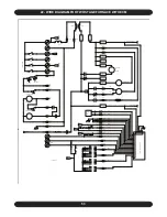
Страница 53: ...53 22 WIRE DIAGRAM FOR TWO STAGE FURNACE WITH ECM...

