7
6(B) MANUFACTURER REQUIREMENTS - GAS
EQUIPMENT VENTING SYSTEM NOT PROVID-
ED.
When the manufacturer of a Product Approved
side wall horizontally vented gas fueled equipment
does not provide the parts for venting the flue gas-
es, but Identifies “special venting systems”, the fol-
lowing requirements shall be satified by the manu-
facturer:
1. The referenced “special venting system” in-
structions shall be included with the appliance or
equipment installation instructions; and
2. The “special venting systems” shall be Product
Approved by the Board, and the instructions for
that system shall include a parts list and detailed
installation instructions.
7. INSTALLATION INSTRUCTIONS:
A copy of all installation instructions for all product
approved side wall horizontally vented gas fueled
equipment, all venting instructions, all parts lists for
venting instructions, and/or all venting design in-
structions shall remain with the appliance or equip-
ment at the completion of the installation.
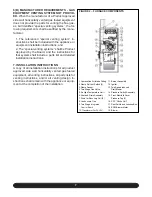
1. Combustion Air Intake Fitting
2. Flame Roll-out Switch (2)
3. Flame Sensor
4. Two Stage Gas Valve
5. Air High Temperature Limit
6. Vent and Drain Assembly
7. Drain for Recovery Coil (2)
8. Condensate Trap
9.
Two Stage
Integrated
Control Board
10. Transformer for 24 VAC
11. Burner Assembly
12. Igniter
13. Two Speed Induced
Draft Blower
14. Pressure Switch Assembly
15. Front Manifold Cover
Pressure Tap (2)
16. PFC “Choke Coil”
17. Door Switch and Junction Box
18. ECM Blower Motor
19. Blower
FIGURE 2 – FURNACE COMPONENTS
Содержание G95V
Страница 27: ...27 FIGURE 21A DIRECT VENT TERMINAL CLEARANCES...
Страница 28: ...28 FIGURE 21B NON DIRECT VENT TERMINAL CLEARANCES...
Страница 53: ...53 22 WIRE DIAGRAM FOR TWO STAGE FURNACE WITH ECM...


