14
Remove the vent connector of the furnace being re-
placed, seal off the inlet to the vent from that furnace,
then test the remaining appliances connected to the
common vent individually following these steps:
1. Permanently seal any unused openings into
the common vent system.
2. Visually inspect the venting system for prop-
er size and horizontal pitch and determine that
there is no blockage, restriction, leakage, corro-
sion, collapsed materials such as fallen bricks,
or any other deficiency that could lead to an un-
safe condition.
3. Insofar as practical, duplicate winter operat-
ing conditions such as closing all windows and
doors in the building. If the remaining appliances
are in a mechanical room, close the door to the
room. Close the fireplace dampers if any, turn on
any appliances that exhaust air to the outdoors
on maximum speed. This would include clothes
dryers, range hoods, bathroom fans, etc. Attic
fans or other fans used only in summer should
be exempted from the test.
8 - VENTING AND COMBUSTION AIR PIPING
4. Follow the lighting instructions of the appli-
ance being tested and turn it on to continuous
operation.
5. Test for spillage at the draft hood relief opening
after 5 minutes of main burner operation. Detect
for spillage using a match flame, taper (candle).
6. After it has been proven that each appliance
to remain connected to the common venting sys-
tem properly vents when tested as listed above,
return the windows, doors, fireplace dampers,
appliances, etc. to the condition they were in
prior to the test.
7. If improper venting is observed during any
of the tests, the common venting system must
be re-sized. In Canada, refer to the latest addi-
tion if CAN/GGA-B149, Natural Gas or Propane
Installation Code. In the United States, refer to
the latest ANSI Z223.1 National Fuel Gas Code
(NEPA 54), or AGA-GAMA Venting Tables for
Category I furnaces.
The furnace products of combustion include both
flue gases and condensate. All venting and drain
materials are plastic.
ACCEPTABLE MATERIALS
IN THE UNITED STATES
For United States installations, the combustion air
and vent piping and fittings may be comprised of:
Schedule 40 PVC, ASTM D1785 or CSA
B137.3
PVC-DWV, ASTM D2665 or CSA B181.2
Schedule 40 CPVC, ASTM F441 or CSA
B137.6
PVC PRIMER AND SOLVENT CEMENT:
ASTM D2564
Follow piping manufacturers instructions on prop-
er installation of piping and fittings including cut-
ting, de-burring, priming, cementing, curing and
supporting.
•
•
•
•
ACCEPTABLE MATERIALS IN CANADA
Effective August 1, 2007, all vent piping materials
and fittings for flue gas venting must be ULC S636
listed and identified as such on the material. The first
3ft. (900mm) of venting must be readily available for
visual inspection. Specified primers and glues of
the certified vent system must be from a single
system manufacture, and not intermixed with other
system manufacture’s vent system parts. The com-
ponents of the certified vent system must not be
interchanged with other vent systems, or unlisted
pipe, and or fittings. Follow the venting manufactur-
ers instructions on installation, cutting, de-burring,
cementing, curing and supporting of the venting
system.
This furnace can be vented with ULC S636 certified
PVC material with a rating of 65º C or more.
The supplied PVC street elbows are certified for
use within the vestibule until July 1, 2008. Use the
approved transition cement certified by the ULC
S636 venting supplier.
Содержание G95V
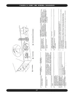
Страница 27: ...27 FIGURE 21A DIRECT VENT TERMINAL CLEARANCES...
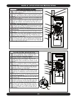
Страница 28: ...28 FIGURE 21B NON DIRECT VENT TERMINAL CLEARANCES...
Страница 53: ...53 22 WIRE DIAGRAM FOR TWO STAGE FURNACE WITH ECM...


