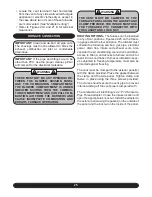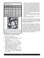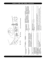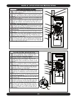
22
12 - TERMINATIONS
IMPORTANT:
The supplied adapter is made of
PVC. If planning to use ABS pipe, use an all-
purpose cleaner and ABS to PVC transition ce-
ment. If planning to use CPVC pipe, use an all-
purpose cleaner, a clear or purple primer and
all-purpose cement approved for the purpose.
Additional information about cleaners, primers,
solvents and cements may be obtained from
their manufacturers.
EXHAUST
HORIZONTAL -
The exhaust termination is nor-
mally a 45° elbow or a medium or long sweep 90°
elbow pointing within 45° of the downward position,
away from the combustion air intake terminal.
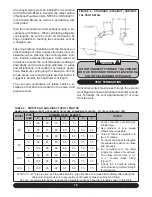
If the required clearance to grade cannot be ob-
tained with the “straight through” configuration, the
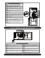
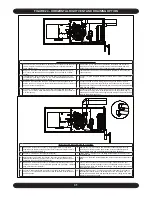
exhaust pipe may be “periscoped” up to 24” to gain
extra height.
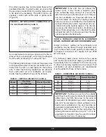
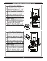
(Figure 9)
In this case, the flue gases
may be expelled horizontally. Use the same size
pipe as the interior run and count the fittings and
length as part of the total vent length.
If winter prevailing wind conditions are variable and
likely to occasionally blow flue gases back in on the
combustion air intake, the exhaust termination may
be raised 18-24” above the combustion air intake
terminal to take advantage of the natural buoyancy
of the flue gases to help prevent re-circulation of
the exhaust.
(Figure 9)
VERTICAL -
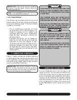
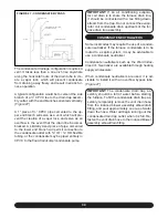
No termination fitting is required if
venting vertically through a roof. The end of the ex-
haust pipe must be 12” higher than the entrance of
the combustion air intake terminal.
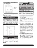
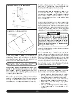
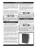
(Figure 11)
The exhaust pipe extending through the roof must
extend a minimum of 18” above any obstruction
within an 18” horizontal distance.
COMBUSTION AIR
HORIZONTAL -
The combustion air termination
is made up of a medium or long sweep 90° elbow
pointing downward to prevent rain from readily en-
tering the combustion air intake piping. An intake
screening is optional; however, unless there is a
compelling reason to use one, the screen may ac-
tually encourage the formation of rime ice, which
could cause the intake to become blocked in cer-
tain weather conditions.
If the required clearance to grade cannot be ob-
tained with the “straight through” configuration, the
combustion air intake pipe may be “periscoped” up
to 24” to gain extra height
(Figure 9)
VERTICAL -
The combustion air termination is
made up of a pair of medium or long sweep 90°
elbow pointing downward to prevent rain from en-
tering the combustion air intake piping. The termi-
nation inlet must be positioned within 3” of the com-
panion exhaust piping.
The combustion air inlet must be located a mini-
mum of 12” above grade, and 12” below the ex-
haust outlet.
(Figure 11)
IMPORTANT:
If the furnace is to be installed in
the vicinity of other fuel burning appliances, ad-
equate combustion air must be available for the
non-direct vent appliances. See Section 10 of
this manual,
“Determining Combustion Air.”
FIGURE 11 - STANDARD VERTICAL VENTING
DETAIL
Содержание G95V
Страница 27: ...27 FIGURE 21A DIRECT VENT TERMINAL CLEARANCES...
Страница 28: ...28 FIGURE 21B NON DIRECT VENT TERMINAL CLEARANCES...
Страница 53: ...53 22 WIRE DIAGRAM FOR TWO STAGE FURNACE WITH ECM...

