49
!
!
7. Keep combustible articles at least 3 feet away
from the furnace. Do not block access for ser-
vicing the furnace Do not use the combustion
air or exhaust piping as a hanger for clothes or
anything else.
IMPORTANT:
Never attempt to operate the fur-
nace without the blower door and combustion
compartment door in place or when the blower
has failed.
ANNUAL INSPECTION/SERVICE
The furnace must be inspected annually by a quali-
fied installation contractor, service agency or fuel
supplier. Your annual inspection will normally cover
the following:
HEAT EXCHANGER -
The heat exchanger should
be inspected for corrosion. The flue passages (heat
exchanger tubes) should be free of scale or exces-
sive corrosion. The top row of heat exchanger tubing
is accessible for cleaning with a small diameter wire-
handled brush by removing the burner assembly. The
bottom row is only accessable if the heat exchanger
is removed and the rear flue box cover is removed.
The recovery coil (secondary heat exchanger) may
be cleaned by accessing the rear flue box cover or
removing the front manifold cover. After clearing ac-
cumulated scale, observe the burner flames. If there
appears to be flame distortion, check the combustion
air intake and exhaust piping and terminals for block-
age. Also check for signs of soot in the condensate
drainage. If flame distortion continues after eliminat-
ing the blockage in the piping as the cause, it may be
necessary to replace the tubular heat exchanger.
NOTE:
Prior to removal of rear flue box cover or front mani-
fold cover, ensure that replacement gaskets are available
to ensure proper sealing of the heat exchanger when re-
assembled.
BURNERS -
The burners should be inspected
to ensure that they are free of deterioration, dust
and debris, and properly aligned with the heat ex-
changer. In most cases, a simple vacuuming with a
brush attachment will adequately clean the burner
assembly and burner compartment.
CAUTION
Be careful when working on the burner
assembly. The hot surface igniter is fragile
and can break easily.
The flame sensor should be inspected and cleaned
with fine steel wool or Scotch-Brite™ scrubbing
pad. The wiring connection should be checked to
ensure that it is tight and corrosion free.
NOTE:
This is a critical connection. Small amounts of cor-
rosion can significantly increase the internal resistance of
the connection. A relatively small increase in resistance
can result in a large decrease in flame signal.
DRAINAGE -
The condensate drainage system
should be inspected and cleaned if necessary. If
the drain trap assembly, or any other component
becomes blocked, condensate may backup into
the secondary or primary heat exchanger causing
nuisance trip-outs of the pressure switches or limit
switch. The condensate should be observed for
signs of dirt, carbon, debris, etc.
If a condensate neutralizer has been added to the
condensate drain, it should be inspected, cleaned,
or the condensate neutralizing media should be re-
placed to ensure clear condensate flow.
INDUCED BLOWER -
The induced blower mo-
tor should be inspected and cleaned if necessary.
Clear any dust buildup from the ventilation ports.
CIRCULATING FAN -
The condition of the circulat-
ing fan should be checked to ensure that it is free of
excessive dust buildup, debris, etc. The mechani-
cal fasteners should be inspected and checked for
proper tightness and parts alignment. The motor
ventilation ports should be cleaned if necessary to
prevent restriction to cooling by air over the motor.
ELECTRICAL -
All electrical connections should
be examined to ensure that they are tight and cor-
rosion free. Repair any connections that have be-
come loose or corroded.
FURNACE OPERATION -
The furnace should be
cycled during the annual inspection and servicing to:
1. Test all safety related controls.
2. Determine that the temperature rise falls
within the range shown on the appliance rating
plate.
3. Ensure that the burner ignition is smooth and
that the flames are smooth soft blue, and not
impinging on the heat exchanger.
Содержание G95V
Страница 27: ...27 FIGURE 21A DIRECT VENT TERMINAL CLEARANCES...
Страница 28: ...28 FIGURE 21B NON DIRECT VENT TERMINAL CLEARANCES...
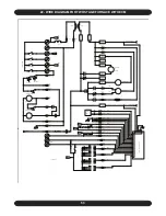
Страница 53: ...53 22 WIRE DIAGRAM FOR TWO STAGE FURNACE WITH ECM...

