41
!
!
be moved to the right hand side. The junction box
contains a BLACK wire to be connected with L1
(hot), a WHITE wire to be connected with L2, the
Neutral, and a GREEN wire to be connected to the
ground.
NOTE:
Use good quality wire nuts such as Marrette® con-
nectors, Ideal® wire nuts, etc.
IMPORTANT:
Use copper conductors only
If the junction box must be moved to the right hand
side of the unit:
1. Unfasten the junction box from the left hand
side.
2. Remove the right side panel knock-out.
3. Remove the junction box cover hook screw
and re-install it on the opposite side of the box.
4. Fasten the junction box to the right hand panel.
NOTE:
L1 (hot) and L2 (neutral) polarity must be
observed when making field connections to the
furnace. The ignition control may not sense flame if
L1 and L2 are reversed. The ground is also essential.
IMPORTANT:
Electrical wiring and components
must be protected from moisture including water
and condensate.
WARNING
THIS FURNACE IS EQUIPPED WITH A BLOW-
ER DOOR SAFETY SWITCH. DO NOT DIS-
ABLE THIS SWITCH. FAILURE TO FOLLOW
THIS WARNING CAN RESULT IN ELECTRI-
CAL SHOCK, PERSONAL INJURY, OR LOSS
OF LIFE.
The low voltage terminals are located in the control
box mounted to the blower assembly. The furnace is
air conditioning ready. Insert the thermostat and air
conditioner contactor low voltage wiring through a
knockout provided in the side panel above the sup-
ply voltage knockout using a field supplied bushing.
Route the control wiring to the control panel to con-
nect to the 24 volt terminal screws.
THERMOSTAT
The room thermostat must be compatible with the
integrated control in the furnace. Electro-mechani-
cal thermostats should be rated 30 V / 1.5 amps.
Most electronic or microprocessor based thermo-
stats except those with “current robbing” circuits
should work satisfactorily. Consult the instructions
of the thermostat manufacturer for technical and in-
stallation details.
Most compatibility problems can be overcome by
the use of an isolation relay. The isolation relay
should be SPST with a 24 volt coil. The switch rat-
ings should be a minimum of 0.5 amps.
(Figure 35)
The thermostat and control wiring should be a mini-
mum of 18 AWG copper. Excessive lengths of wire
may result in enough voltage drop to impair the
proper functioning of the furnace. For thermostat
wires in excess of 25 feet, use 16 AWG; 50 feet,
use 14 AWG.
SINGLE STAGE THERMOSTAT
The automatic heat staging option allows a single
stage thermostat to be used with a two stage fur-
nace. The control provides a movable jumper (P5)
to select between 5 minute and *10 minute auto-
matic staging. Automatic staging time begins when
the blower is energized after the heat blower delay
period. If the jumper is in the 5 minute position, the
control will automatically start high heat after 5 min-
utes of continuous low heat operation. If the jumper
is in the *10 minute position, the control will auto-
matically start high heat after 10 minutes of contin-
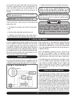
FIGURE 37 - ISOLATION RELAY
17 - LOW VOLTAGE WIRING
Содержание G95V
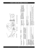
Страница 27: ...27 FIGURE 21A DIRECT VENT TERMINAL CLEARANCES...
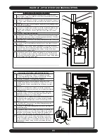
Страница 28: ...28 FIGURE 21B NON DIRECT VENT TERMINAL CLEARANCES...
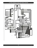
Страница 53: ...53 22 WIRE DIAGRAM FOR TWO STAGE FURNACE WITH ECM...

