35
!
!
!
!
GAS SUPPLY
WARNING
THIS FURNACE IS FACTORY EQUIPPED TO
BURN NATURAL GAS ONLY.
CONVERSION TO LP GAS REQUIRES SPECIAL
NATURAL GAS TO LP CONVERSION KIT.
FAILURE TO USE THE PROPER CONVERSION
KIT CAN CAUSE FIRE, EXPLOSION, CARBON
MONOXIDE POISONING, PROPERTY DAM-
AGE, PERSONAL INJURY OR LOSS OF LIFE.
IMPORTANT:
Conversion of this furnace re-
quires specialized equipment. Conversion must
be completed by a trained and qualified installer,
service agency or gas supplier.
IMPORTANT:
Connect this furnace only to gas
supplied by a commercial utility or supplier. Pri-
vate gas wells do not generally provide gas with
consistent, uniform and predictable heating val-
ues and densities. Many non-commercial wells
contain impurities such as sulphur, which may
damage the furnace. This furnace cannot oper-
ate properly or safely using fuels outside normal
commercial standards.
GAS PIPING
In Canada, the gas piping should be installed in ac-
cordance with CAN/CGA-B149.1 and 2, and in ac-
cordance with any local codes.
In the United States, the gas piping should be in-
stalled in accordance with NFPA 54 / ANSI Z223.1
and any local codes.
If local codes allow the use of a flexible gas appli-
ance connector, always use a new listed connector.
Do not use a connector, which has previously ser-
viced another gas appliance.
IMPORTANT:
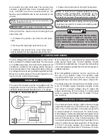
To maintain a good seal in the
burner area, the gas piping through the side
panel into the furnace must be ½” A53 black iron
pipe. The pipe passes through a special rubber
grommet that is custom manufactured to seal
tightly around the gas pipe.
The gas piping may enter the furnace from either
side. Once the routing of the gas pipe is deter-
mined, select and remove the applicable knockout
and install the grommet within the hole.
Install a BMI ground joint union between the gas
valve and the side panel to allow easy removal of
the burner for service purposes.
IMPORTANT:
Always use a backup wrench to
prevent twisting of the control assembly and gas
valve. Any strains on the gas valve can affect
positioning of the orifices relative to the burners.
This could result in faulty burner operation.
Install a manual gas shut-off valve and dirt pocket
as close to the furnace as possible. Some local
codes call for the manual gas shut-off valve to be
located between 4 to 5 feet above floor level to pre-
vent tampering by small children. Ensure that the
valve is readily accessible.
IMPORTANT:
Ensure that the manual shut-off
valve and gas valve are not subjected to high
pressures.
WARNING
DISCONNECT THE MANUAL SHUT-OFF
VALVE AND GAS VALVE DURING ANY PRES-
SURE TESTING THAT EXCEEDS ½ P.S.I.G.
(3.45 KPA).
14 - GAS SUPPLY AND PIPING
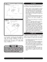
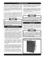
FIGURE 28 - FURNACE GAS PIPE CONNECTIONS
(NOTE RUBBER GROMMET)
Содержание G95V
Страница 27: ...27 FIGURE 21A DIRECT VENT TERMINAL CLEARANCES...
Страница 28: ...28 FIGURE 21B NON DIRECT VENT TERMINAL CLEARANCES...
Страница 53: ...53 22 WIRE DIAGRAM FOR TWO STAGE FURNACE WITH ECM...

