9
4 - LOCATION OF UNIT
1. GENERAL GUIDELINES
a. Select a location where the exhaust and com-
bustion air piping can be routed between the
furnace and their terminations with a minimum
of lengths and fittings. Be sure to check that the
proposed termination location will meet code
requirements with respect to location and mini-
mum clearances.
(See venting section for mini-
mum and maximum limits.)
b. Select a location as near as possible to the
existing or proposed duct system.
c. The furnace location must have provisions for
condensate drainage. If a suitable drain is un-
available near the furnace, a condensate pump
must be used. The condensate pump drain tub-
ing must not terminate outdoors; similar to some
air conditioning condensate installations. Be
sure to select a condensate pump that has been
approved for furnace condensate applications.
d. The furnace location must permit access for
servicing and be within the clearance to com-
bustibles guidelines as marked on the appliance
rating plate.
e. The furnace must be installed level to allow
for the proper drainage of condensate. The fur-
nace may shut down during winter operation if
the condensate does not drain freely away from
the furnace.
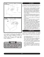
FIGURE 3 - SUGGESTED METHOD FOR SUSPENDING HORIZONTAL FURNACE
f. The furnace should be installed on a firm base
when installed in the upflow position. This would
typically be the concrete floor if installing the fur-
nace in a basement.
g. If the furnace is being installed so that the re-
turn air will enter through the bottom, the perim-
eter of the furnace must be properly supported.
h. When installed in the horizontal position, the
furnace may be supported from the bottom, or
suspended.
(Figure 3)
i. If the furnace is to be installed in a commercial
(repair) garage, the burners and ignition source
must be a minimum of 4½ feet (1375 mm) above
the floor. The furnace must be protected from
physical damage by metal barriers or other ac-
ceptable means.
2. OTHER CONSIDERATIONS
a. If the furnace is to be located in an area where
the combustion air is laden with chemical com-
pounds such as bromine, chlorine or fluorine, as
may be found in swimming pool chemicals, laun-
dry detergents, etc., use outdoor air for combus-
tion. These compounds when exposed to flame,
form acids which attack the heat exchanger and
other components.
A partial list of contaminants would include:
Aerosols, particularly CFC based aerosols
Air fresheners
“Airplane” glue and similar cements
•
•
•
Содержание G95V
Страница 27: ...27 FIGURE 21A DIRECT VENT TERMINAL CLEARANCES...
Страница 28: ...28 FIGURE 21B NON DIRECT VENT TERMINAL CLEARANCES...
Страница 53: ...53 22 WIRE DIAGRAM FOR TWO STAGE FURNACE WITH ECM...


