25
!
!
!
!
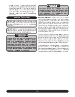
Locate the vent terminal 3 feet horizontally
from the vent of any side wall vented fuel gas
appliance or electric clothes dryer, except in
the case where two or more of these furnaces
are multi-vented.
(See “Multiple Venting”)
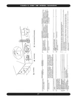
Refer to Figures 21A and 21 B for terminal
clearances.
FURNACE CONNECTION
IMPORTANT:
Clean and de-burr all pipe cuts.
The shavings must not be allowed to block the
exhaust, combustion air inlet or condensate
drain lines.
IMPORTANT:
If the pipe and fittings are to be
other than PVC, use the proper cleaner, primer
and cement for the dissimilar materials.
WARNING
THERE MUST NOT BE ANY OPENINGS BE-
TWEEN THE BLOWER DIVISION PANEL
AND THE COMBUSTION COMPARTMENT.
THE BLOWER COMPARTMENT IS UNDER
GREATER SUCTION THEN THE COMBUS-
TION COMPARTMENT AND CAN PULL COM-
BUSTION AIR FROM THE BURNERS AND
CAUSE INCOMPLETE COMBUSTION AND
ERRATIC FURNACE OPERATION.
•
•
•
WARNING
THE VENT MUST BE CLAMPED TO THE
FURNACE PANEL USING THE GASKET AND
CLAMP PROVIDED. THE INTAKE MUST USE
THE THREADED PVC CONNECTOR WITH
THE GASKET AND LOCK NUT.
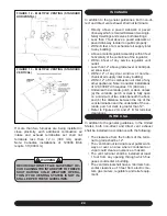
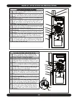
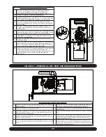
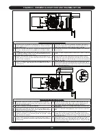
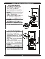
ROUTING OPTIONS -
The furnace can be installed
in any of four positions. Figures 22-25 on the follow-
ing pages show the four positions. The installer must
consider the following services: gas pipe, electrical
power, drain trap, intake and exhaust vents. Also
consider the air conditioning connections and drain,
access to filter(s) and access to furnace and a/c for
repair. Drains and traps of furnaces installed in spac-
es subjected to freezing temperature must also be
protected against freezing.
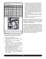
The vent must be clamped to the exterior panel(s)
with the clamp provided. Place the gasket between
the clamp and the side panel. Tighten clamp and
fasten in place using the three screws provided.
The clamp should secure the vent pipe to prevent
internal damage if the vent pipe is tampered with.
The combustion air inlet fitting is a 2” PVC Socket to
Pipe Thread adapter. Chose the intake location and
open the appropriate knock out. Install the adapter to
the exterior panel using the gasket (on the outside of
the panel and the locknut on the inside of the panel.
Содержание G95V
Страница 27: ...27 FIGURE 21A DIRECT VENT TERMINAL CLEARANCES...
Страница 28: ...28 FIGURE 21B NON DIRECT VENT TERMINAL CLEARANCES...
Страница 53: ...53 22 WIRE DIAGRAM FOR TWO STAGE FURNACE WITH ECM...

