45
!
!
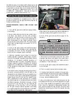
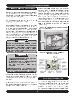
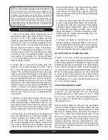
2. Insert a duct thermometer in the return air
duct as close to the furnace as practical. Ensure
that the thermometer location will be unaffected
by humidifier bypass ducts, etc. Choose a loca-
tion well within the main air stream.
3. Operate the furnace long enough to obtain
steady state conditions at both input rates (High
Fire and Low Fire).
4. When the two thermometers have stabilized,
usually within 5-8 minutes, compare the two
readings. Subtract the return air temperature
from the supply air temperature. The difference
is the temperature rise, also called ∆T.
5. Compare the measured ∆T to the tempera-
ture rise range shown on the rating plate.
Unless stated differently on the rating plate,
the temperature rise should normally range
between 35° to 65°F High Fire, 25° to 55°F Low
Fire. When adjusting the temperature rise, the
ideal temperature is approximately mid-range.
If the measured ∆T is above the approved
temperature range, there is too little air flow. It
must be increased by selecting the appropriate
“HEAT” jumper setting , removing restrictions
in the ductwork, or adding supply or return
ductwork.
If the measured ∆T is too low, there is too much
air flow.
CALCULATING AIR FLOW
There are circumstances where it may be desir-
able to know the air flow delivery through the duct
system, such as when estimating the amount of air
flow available for air conditioning. This can be done
by direct measurement with electronic or sloped
manometers and velometers, or by counting the
number of times the amber CFM LED on the
control board flashes. Each flash signifies 100
CFM; count the flashes and multiply by 100 to
determine the actual CFM delivered (for example:
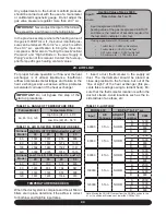
10 flashes x 100 = 1000 CFM). Or use the formula
in the next column.
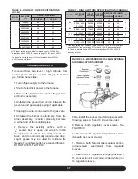
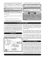
CFM =
Output
1.085 x
∆T
where:
CFM is airflow in cubic feet per minute;
∆T is the temperature rise; and
O
utput is the furnace output capacity from
the rating plate
.
•
•
•
NOTE:
Output will vary directly with the input. If the
actual input is below the stated input, the output will
be reduced in the same ratio (93%).
ADJUSTING BLOWER SPEEDS
WARNING
DISCONNECT THE ELECTRICAL SUPPLY TO
THE FURNACE BEFORE ATTEMPTING TO
CHANGE THE BLOWER SPEED. FAILURE
TO DO SO COULD RESULT IN ELECTRICAL
SHOCK RESULTING IN PERSONAL INJURY
OR LOSS OF LIFE.
This unit is factory set to run at the middle of the
heating temperature rise range as listed on the
rating plate. The cooling speed is set to the maxi-
mum airflow designated in the model number.
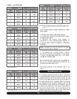
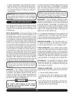
Three sets of 4 position movable jumpers are
provided for Heat, Cool, and Adjust taps for a
variable speed motor. These tap jumpers apply
signals to the ECM motor without other interac-
tion with the control board.
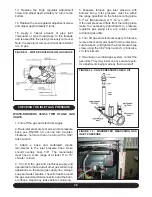
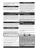
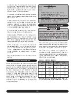
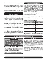
TABLE 2 - HEATING SPEEDS
ALL MODELS
ESP 0.1” to 1.0” w.c.
HEAT
Jumper
ADJUST
Jumper
Low-Fire ▲T
Range 25-55 °F
High-Fire ▲T
Range 35-65 °F
A
NORM
40 °F
50 °F
B
NORM
35 °F
45 °F
C
NORM
45 °F
55 °F
D
NORM
50 °F
60 °F
Note: Moving the ADJUST jumper from the NORM position to the
(+) or (-) position will increase or lower thetemperature rise by 15%
Содержание G95V
Страница 27: ...27 FIGURE 21A DIRECT VENT TERMINAL CLEARANCES...
Страница 28: ...28 FIGURE 21B NON DIRECT VENT TERMINAL CLEARANCES...
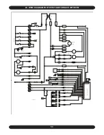
Страница 53: ...53 22 WIRE DIAGRAM FOR TWO STAGE FURNACE WITH ECM...

