background image


Installation, Operation and 

 Service Manual 


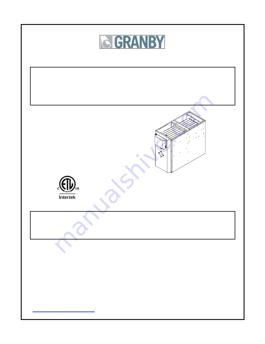
       KLC  

 Condensing Unit 

          95% + EFFICIENCY 
OIL FIRED

 LOWBOY FURNACE 


     Model KLC- 100 


CONFORTO CHE  


INSTALLATIONS MUST MEET ALL LOCAL AND FEDERAL 

CODES THAT MAY DIFFER FROM THIS MANUAL 


Please read the manual in its entirety before beginning installation. 

This manual must be kept with the furnace for future reference


GRANBY FURNACES INC. 

PO Box 637 
12118 Hwy 209 
Parrsboro Nova Scotia Canada 
B0M 1S0 


902-254-2543 

www.granbyindustries.com


   01-24-2014


G2012-E3 Rev.G


Summary of Contents for KLC-100

Page 1: ...T MEET ALL LOCAL AND FEDERAL CODES THAT MAY DIFFER FROM THIS MANUAL Please read the manual in its entirety before beginning installation This manual must be kept with the furnace for future reference...

Page 2: ...temperature probe in the flue pipe Upon completion of the test cover the hole with HVAC aluminum tape If the temperature is OVER 125 Degrees F 1 Check that ALL 20 baffles are in place To do this you...

Page 3: ...ALLATION OF THE BURNER 13 5 2 SET BURNER FOR EFFICIENT OPERATION 14 5 3 TECHNICAL INFORMATION 16 6 0 FURNACE OPERATION AND SETTINGS 17 6 1 BLOWER SETTING 17 6 2 FAN TIMER CONTROL BOARD ST9103 A 1028 1...

Page 4: ...E DO NOT TAMPER WITH THE FURNACE OR CONTROLS CALL A QUALIFIED BURNER TECHNICIAN DO NOT STORE OR USE GASOLINE OR OTHER FLAMMABLE VAPOURS AND LIQUIDS IN THE VICINITY OF THIS UNIT OR ANY OTHER APPLIANCE...

Page 5: ...t capacity 3 0 tons Maximum air temperature rise See pages 16 and 31 High Limit temperature 215 F Thermostat anticipator See thermostat instructions MOTOR BLOWER KLC 100 1 2 hp ECM GT12 10 FAN HIGH LI...

Page 6: ...2 x 12 x 20 x 2 non pleated UL approved PLENUM DIMENSIONS KLC 100 CONFORTO Cold air return A 20 x 20 508 x 508 mm Hot air supply B 20 x 20 508 x 508 mm Plenum spacing C 3 76 mm KLC 100 DIMENSIONS Dime...

Page 7: ...eck for kinks in the oil lines as well as for possible air pockets and for loose connections Two filters as shown below are recommended Optional tank gauge protectors and outlet protectors are availab...

Page 8: ...CREASE THE OUTLET TEMPERATURE A MODIFIED UNIT IS NO LONGER ENERGY STAR APPROVED THIS COULD RESULT IN FIRE HAZARD AND OR OTHER HAZARDOUS CONDITIONS THAT MAY LEAD TO BODILY HARM COMBUSTION Install openi...

Page 9: ...tion of the installation must be used 3 3 INSTALLATION INFORMATIONS VENT PIPE See NFPA 31 USA or CSA B139 Canada code Breech is certified for 3 ULC IPEX S636 PVC 40 vent pipe in Canada and IPEX S636 P...

Page 10: ...1 2 BF3 Riello burner approved Two small openings of 3 1 2 BF3 Riello burner approved Especially for retrofit installation Easy to fit one pipe in 7 x7 chimney tile Avoid wall opening No clearance res...

Page 11: ...EARANCE TWO PIPES WALL CLEARANCE All piping must be on same wall 0utlet termination clearance above grade and roof overhang Check flue and combustion air pipes for any leak VENT TERMINATION WARNING It...

Page 12: ...rain tube Floor drain or condensate pump reservoir BEWARE NOT TO CREATE A KINK IN THE CONDENSATE DRAIN TUBE IMPROTANT Floor drain Or condensate pump reservoir Please note that the warranty to this pro...

Page 13: ...orten the unit life and may cause products of combustion to enter the house Wire as per wiring label and diagram Height of the coil above the unit supply shall be at least 4 102 mm See A C coil Manufa...

Page 14: ...correct setting INSERTION MOUNT BURNER Tighten top nut first so burner tips down slightly The burner is always installed in an upright position by four 4 nuts PUMP BY PASS For one pipe system factory...

Page 15: ...ed for the burner set up Drill 3 8 diameter hole on top of the vent pipe and use the supplied test port plug to seal after burner setup Rear Flue Furnace illustration COMBUSTION TEST All your tests mu...

Page 16: ...band on the burner to reduce your CO2 lecture by 1 5 with a two pipes installation On a one pipe installation reduce your CO2 by 1 You now have a perfect 0 of smoke Relation between of CO2 and O2 CO2...

Page 17: ...2 wc to 0 5 wc Temperature Rise F 52 85 58 85 52 85 58 85 Blower Speed MEDIUM MEDIUM MEDIUM MEDIUM Static Pressure Blower ECM 1 2 hp Speed 0 2 wc 0 5 wc HI 1300 1230 MHI 1225 1160 MED 1140 1050 MLO 1...

Page 18: ...perates as usual OPERATION If the furnace system fails to operate or operates in an unusual manner call your service technician If the burner fails to operate at any time call a qualified burner techn...

Page 19: ...m at the end of the heating cycle after the burner has turned off adjust the FAN OFF dip switch on fan timer control board Refer to the next figure FAN OFF Dip Switch Dip Switch adjustment 90 seconds...

Page 20: ...Burner shuts down after call for heat is satisfied 5 Blower stops according to adjusted FAN OFF Dip switch selection ST9103 Cooling Sequence 1 Thermostat calls for cooling 2 Blower starts immediately...

Page 21: ...l Yes Move to next step No Check for bad connection Yes Move to next step No Change Transformer 3 Electronic Fan control Check for 24 Volts between R and C Yes Move to next step No Change the electron...

Page 22: ...Check for 120 Volts on the contact No of burner activation relay Yes Move to next step No Change the burner activation relay Check for 120 Volts on terminal 1 of the bypass timer relay 15sec Yes Move...

Page 23: ...he electronic fan control Yes Check COOL speed on the blower motor No Change the electronic fan control 8 Condensing unit Check for 24 volts between terminal Y and C on the electronic fan control Yes...

Page 24: ...31 for recommended servicing procedure Clean flue pipes on a regular basis Check flue and combustion air pipes for any leak CHANGING NOZZLE It is recommended that the nozzle be replaced once a year If...

Page 25: ...alizer cartridge can be acquired from your local dealer During the first hours of operation The appliance self cleans its interior The result being that for the first 20 hours of activity the condensa...

Page 26: ...ent 3 Disconnect the wiring to the blower motor 4 Remove the air filter and the condensate neutralizer 5 Remove the four 4 wing nuts securing the blower side to the base panel bracket 6 Slide the blow...

Page 27: ...L WIRING DIAGRAM 8 1 HEATING COOLING The condensate overflow switch is inside the rear black plastic condensate collector It is a normally automatic reset contact NOTE 1 2 wires thermostat wiring diag...

Page 28: ...27 8 1 HEATING ONLY The condensate overflow switch is inside the rear black plastic condensate collector It is a normally automatic reset contact...

Page 29: ...28 9 0 EXPLODED PARTS VIEW KLC 100 CONFORTO Exploded Parts View...

Page 30: ...r Gasket 20 Holes 1 18 HEX A0 0002 00 Condensing Heat Exchanger Assembly 1 19 3AF 02 1220 01 Filter Air 12 x 20 x 2 Non Pleated Strata Type 2 20 INS P0 0018 00 Sight Glass Insulation 1 21 INS P0 0017...

Page 31: ...O BF 3________ Turbulator Air Gate Venting type installation Two pipe system______ Coaxial System ______ Vertical one pipe system ________ Smoke result 0 TRACE__________ Combustion Results CO2 Excess...

Page 32: ...Supply Pressure Ps Return Pressure Pr A C Coil Total Resistance Reading A C coil total resistance Coil Pressure Pc Supply Pressure Ps Temperature Rise Reading Temperature rise Supply Temp Ts Return T...

Page 33: ...Canada and the United States through a distribution network Our team of engineers designers and technicians continually research and develop products to go beyond the demanding specifications of today...

Reviews: