background image


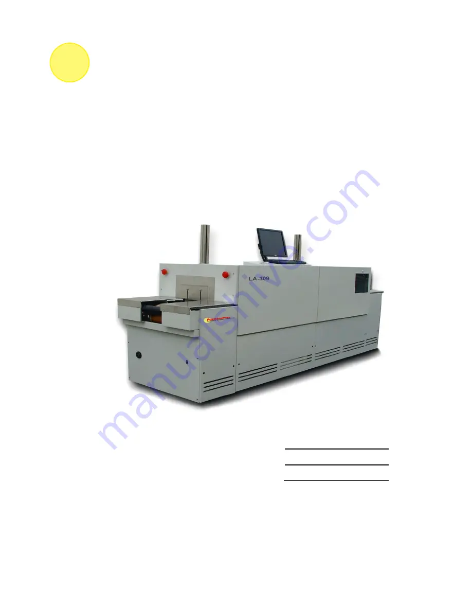
CONTINUOUS BELT IR FURNACE 

Model LA-309 


Owner’s Manual 

Revision 3 


MODEL: 

LA-309 

SERIAL NUMBER: 

1303091001 

FACTORY ORDER NUMBER: 

10-004 


LCI FurnacePros 

30025 Alicia Pkwy, #417 

Laguna Niguel,  CA 92677 USA 

+1 (949) 218-4996 

Email: [email protected] 


FurnacePros 

DIVISION OF LOCHABER CORNWALL, INC. 

Summary of Contents for LA-309

Page 1: ...er s Manual Revision 3 MODEL LA 309 SERIAL NUMBER 1303091001 FACTORY ORDER NUMBER 10 004 LCI FurnacePros 30025 Alicia Pkwy 417 Laguna Niguel CA 92677 USA 1 949 218 4996 Email service furnacepros com FurnacePros DIVISION OF LOCHABER CORNWALL INC ...

Page 2: ...thor shall be liable for damages arising herefrom Warranties for FurnacePros or Lochaber Cornwall Inc products and services shall be limited to those are set forth in the express warranty statements accompanying such products and services Nothing herein should be construed as constituting an additional warranty THERE ARE NO OTHER WARRANTIES EXPRESS STATUTORY OR IMPLIED INCLUDING THOSE OF MERCHANTA...

Page 3: ...umber 1 ea LA 309 Furnace 10 004 LA 309 1 ea Monitor Dell P170 17 LCD Professional Flat Panel 1 Length Belt segment with splice wire 1 ea Latch and Key Flowmeter alt to installed twist latch 1 ea Mouse USB Optical 2MOUSEU2L In addition verify that you received the following shipped separately Qty Unit Description Part Number 2 ea Manual Owner s 3 Ring Bound 10 004 676 110000 02 2 ea Manual Referen...

Page 4: ...removed Electrical shock hazards exist for those technicians who service the furnace High voltages are required to operate the furnace and precautions must be taken to reduce the exposure to these elements Again it is the responsibility of the furnace owner to assure that only properly trained service technicians familiar with high voltage operations be allowed to service the equipment EXPLOSION E...

Page 5: ...10 004 676 110000 v WARRANTY Warranty goes here ...

Page 6: ...vi LA 309 Owner s Manual ...

Page 7: ...4 2 7 Alarm Status All Access Levels 2 16 2 8 Data Log Alarms and Alerts 2 16 2 9 Over Temperature Alarm Operation option not included 2 18 2 10 Remote Access 2 19 2 11 View Alternate Programs 2 19 2 12 Element Monitors 2 20 Section 3 3 1 SERVICE TROUBLESHOOTING 3 1 3 1 Routine Maintenance 3 1 3 2 Service and Maintenance Access 3 1 3 3 Daily Maintenance 3 1 3 4 Monthly Maintenance 3 2 3 5 Other Sc...

Page 8: ... 77184 Controlled Atmosphere Infrared Dryer 4 1 Section 5 5 1 ENGINEERING 5 1 5 1 Power and Current 5 1 5 2 Fuses 5 1 5 3 TB1 Overview 5 1 5 4 TB2 Overview 5 1 5 5 TB3 Overview 5 1 5 6 Process Gas Flow 5 1 5 7 Channel Assignments 5 1 Section 6 6 1 DRAWINGS SCHEMATICS 6 1 Section 7 7 1 MATERIAL SAFETY DATA SHEETS 7 1 7 1 FURNACE MSDS 7 1 Section 8 8 1 APPENDIX A 8 1 8 1 TEC10 INTERFACE MODULE CALIB...

Page 9: ...and Air Purge 1 5 Figure 1 2 14 Belt Splice 1 5 Figure 1 2 15 Shipping Brackets 1 5 Figure 1 2 16 Computer Unswitched 1 6 Figure 1 3 1 Name Plate 1 6 Figure 2 1 1 Control Panel showing Furnace Power ON and OFF and Indicator Lights 2 1 Figure 2 1 2 Control Panel Rear showing monitor and USB ports 2 1 Figure 2 1 3 Control Panel 2 1 Figure 2 2 1 Screen Button Menu 2 5 Figure 2 2 2 Security Screen Log...

Page 10: ... Alarm switch 3 25 Figure 3 17 2 Air Pressure sensor 3 25 TABLES Table 2 1 Main Furnace Power 2 2 Table 2 2 Starting the Furnace 2 4 Table 2 3 Gas Supply Pressure 2 6 Table 2 4 Restarting the Furnace after Auto Shut Down 2 11 Table 2 5 PID Initial Settings 2 14 Table 2 6 Initial Alarm Settings 2 17 Table 3 1 Recommended Maintenance Frequency 3 2 Table 3 2 PLC Opto22 Troubleshooting Guide 3 10 ...

Page 11: ...10 004 802 101524 TB3 OVERVIEW Section 5 10 004 802 101560 GAS FLOW Section 5 10 004 802 101520 CHANNEL ASSIGNMENTS Section 5 10 004 803 091734 FURNACE ARRANGEMENT LA 309 Section 6 10 004 803 091734 1 INTERFACE ROLLER LOCATION Section 6 STD 803 10100 PRODUCT CLEARANCE Section 6 10 004 802 101701 PLC CONFIGURATION Section 6 STD 802 101770 01 POWER CONTROL SCHEMATIC Section 6 STD 802 101771 FRAME WI...

Page 12: ...Contents xii LA 309 Owner s Manual ...

Page 13: ...er electrical compartment for shipping damage loose connections or components Finally inspect the furnace interior checking for broken lamps foreign objects or any components that may have come loose during shipment Report any shipping damage immediately to the FurnacePros Technical Support Department 1 2 Installation Requirements 1 2 1 Machine Location Furnace Environment Considerations Location ...

Page 14: ...ove the base covers and adjust the leveling screws to level the frame within 0 06 inch overall Each of the leveling screws should support an equal amount of weight After the frame is level Adjust the chamber leveling screws to 0 06 inch overall Figure 1 2 1 Leveling Feet Figure 1 2 2 Leveling Chamber Supports 1 2 3 Removal of Shipping Restraint Screws Large furnaces operating at high temperatures ...

Page 15: ... the provided disconnect enclosure Remove the upper and lower panels numbers 4 and 11 ref 802 101401 01 PANEL LAYOUT The disconnect switch must be turned to OFF to remove the lower panel Locate the disconnect enclosure behind the lower panel and remove its cover by loosening the two screws Remove one of the knockouts in the top of the enclosure use center 1 opening for four 4 8 AWG wires or larger...

Page 16: ...be above the dew point of the room air to prevent condensation from forming on the feed lines and dripping into the furnace WARNING The flowmeters on these furnaces are rated at 70 psi maximum Operating above 70 psi exposes the operator to possible injury 1 2 7 Process Exhaust Requirements In most applications process exhaust and heat should be vented to the outside atmosphere It is the customer s...

Page 17: ...alling the belt it will be helpful to have an assistant available to help guide the belt into the furnace entrance The portion of the belt which goes through the furnace is rolled up and secured at the entrance end of the furnace Unroll the belt and attach it securely to the pull wire that was left in the furnace chamber Pull the belt through the chamber from the exit end of the furnace while an a...

Page 18: ... the UPS serial or USB connector into the rear panel of the computer tower To install the manufacturer s software insert the UPS Installation Disk in the optical drive accessed through the computer access opening below and left of the control console Follow UPS manufacturer s instructions for proper installation and configuration of the UPS to allow normal computer system shutdown in the event pow...

Page 19: ...o Check confirm voltages o Re calibrate all SCR s o Re calibrate belt Verify tracking o Check operation of Ultrasonic Cleaner Dryer system Verify valve and equipment sequencing water pressure Leak check water system Verify timer settings for UCD clock start and drain o Check operation of Over Temperature system Adjust as necessary o Purge air tank Leak check air system Cycle machine to a fully ope...

Page 20: ...Section 1 1 8 LA 309 Owner s Manual ...

Page 21: ...rol circuits are energized and indicates that power is available to actuate the control circuits Figure 2 1 1 Control Panel showing Furnace Power ON and OFF and Indicator Lights Figure 2 1 2 Control Panel Rear showing monitor and USB ports ALARM HORN Black Audible Alarm This horn provides audible feedback for furnace system alarm conditions UCD Fill Run Drain Indicating Lamps option not included L...

Page 22: ...s located in the doors are released 24 Vac controls active only if EMO and panel interlocks allow 1 K2 mechanical relay latches up FURNACE POWER light green on 2 K6 mechanical relay sends switched 117 Vac power to belt motor Opto22 gas supply valves EM and hour meter 3 K3 contactor energizes phase transformers TR1 TR2 TR3 all 117 and 24 Vac power control signals and accessories turn on Cuts power ...

Page 23: ...nace is in WARM UP or PROCESS READY modes 1 provides power to K6 mechanical relay and K3 contactor until temperature reading in all zones 100C then 2 shuts off K6 and K3 see FURNACE POWER button OFF Otherwise no effect COMPUTER POWER The computer has been wired to be powered from an un switched power source COMPUTER UNSWITCHED Default As delivered the computer and monitor are wired to remain ON un...

Page 24: ...oftware starts Computer and PLC begin to communicate 4 Monitor ON Press the power button on the monitor if you do not see the logo screen 5 Start Program Press Furnace program icon to initialize communication with the PLC and start the furnace program Log in to furnace software Log in is only possible when PLC and Computer are communicating CAUTION Dangerous voltages are now present throughout the...

Page 25: ...th its own password See the Furnace Reference Manual Chapter 5 Software for information on managing users and passwords Figure 2 2 2 Security Screen Log on Access Level 1 password 1 Operator level and allows the operator to load and run a recipe and initiate a process Initial password is set to 1 Access Level 2 password 2 Tech Engr level It allows the Technician or Engineer to do all of the above ...

Page 26: ...s Regulator 70 110 psig 4 8 7 6 bar Furnace Regulator optional 60 70 psig 4 1 4 8 bar Low Pressure Alarm Switch 55 psig 3 8 bar See Section 3 for information calibration and service of the pressurized gas N2 CDA system WARNING The flowmeters on these furnaces are rated at 70 psi maximum Operating above 70 psi exposes the operator to possible injury Flow Meter Default Settings Select the Gas Flow b...

Page 27: ... the Deviation screen by clicking on the Deviation button The screen will show the deviation of measured temperature from set point for each zone The vertical bars are green for process ready conditions by zone and change color independently as the deviation in a given zone changes The user can drag the Deviation screen to another location on the Process Screen or close the screen at any time 3 Ch...

Page 28: ...er applied to the zone and the lamp power of the zone This number can be limited by the Maximum power value set up in the SCR Calibration screen If this value is set at 0 no power is calculated and no limit is set on the power used by the machine Any non zero value will cause the system to calculate the power and limit it to this value Default maximum power is set to 50 NOTE Edge heaters are not p...

Page 29: ...roduct cooling fans and keep process gas flowing during COOL DOWN 2 When all zones are below 100 C COOL DOWN is complete The furnace may be left in this condition with belt running and process gas flowing indefinitely You may manually turn off the process gas flow at this point without causing harm to the furnace although you must remember to turn it back on prior to restarting the furnace 3 To re...

Page 30: ...ll still be flowing to the furnace until the valve is manually closed The furnace can be left in this state for considerable time without harm to the furnace For complete shutdown of the furnace see 2 4 6 Complete Shut Down 2 4 6 Complete Shut Down For complete shutdown of all systems and power to the furnace follow steps 1 5 Table 2 4 Complete Shut Down Summary 1 Cool Down Click COOL DOWN on the ...

Page 31: ...sktop select start then select Shut Down The computer will Power OFF after the operating system closes all files 2 4 8 Exit Furnace Program 1 EXIT FROZEN PROGRAM Using the PC keyboard press ALT F4 to exit the active program 2 This method of closing the furnace program should only be used to exit a frozen program It will not affect the program running in the PLC If still in Cool Down the furnace wi...

Page 32: ... to close the active window If Alt F4 does not close the main furnace program repeat the Alt F4 command until you see the Exit OptoDisplay Runtime dialog box Do not restart the furnace program until the furnace is ON 2 Main Power Verify the Main Power ON button is lit Disconnect switch should be on all panels in place and EMO switches reset 3 Furnace ON Press Furnace Power ON button Furnace ON lig...

Page 33: ...ill allow the operator to edit and save recipe data When initializing the Load Run field the process screen is updated and the Recipe Setup screen is changed to On Line Edit Figure 2 5 1 Recipe Screen 2 Load Recipe Access Levels 1 and 2 3 Delete Recipe Access Level 2 4 Edit Stored Recipe Save Stored Recipe Access Level 2 NOTE Do not use this feature on the current recipe while in ready mode and wh...

Page 34: ...gth of the heated chamber They can be used to improve the temperature uniformity across the width of the belt Click on the blue cell to modify the percentage on The range is 0 100 and can be set in increments of 1 See the Reference Manual for more on using the edge heaters 2 6 2 PID Zone Tuning Access Level 2 On the recipe screen click on the desired Edit Zone PID Setting pushbutton A Zone Tuning ...

Page 35: ... rate function that clamps temperature overshoot oscillation The maximum set point for the derivative function should be of the integral value 2 6 3 Change Transport Speed Access Level 2 Place the cursor on the Belt Speed field click type in the new value and press enter from the keyboard NOTE Transport speed is displayed in inches per minute 2 6 4 Change Gas Flow Settings This screen represents f...

Page 36: ... screen To clear or silence an alarm alert move the cursor to and click on Acknowledge Events See Section 3 SERVICE TROUBLESHOOTING for further information 2 8 Data Log Alarms and Alerts 2 8 1 Occurrence and Timed Logging Control Access Levels 1 and 2 Move the cursor to and click on Logging to see any occurrence Figure 2 8 1 Event Logging 2 16 LA 309 Owner s Manual ...

Page 37: ...the switch counter clockwise to decrease the pressure set point so the alarm will not occur until the pressure drops to a lower point 2 8 3 Auto Gas Shutoff Included option This furnace may be equipped with Auto Gas Shutoff The Auto Gas Shutoff feature consists of solenoid valves on the process gas supply lines integrated with the furnace These valves open and allow Process Gas to flow when Furnac...

Page 38: ...passes a temperature signal to the digital panel meter The operator can view the temperature on the panel meter and the respective zone being monitored will be indicated on the scanner ALARM If the temperature in any zone reaches the alarm set point an alarm will sound in the scanner annunciator and the furnace will go into Cool Down the heating elements will be shut off by the controller To silen...

Page 39: ...he LogMeIn com internet service for remote diagnostics If the computer is LogMeIn enabled Make sure there is an internet connection to the local network connection 2 port Click on the blue LogMeIn icon in the menu or next to clock on desktop menu bar Click Overview Click TURN ON button Note When TURN OFF button is shown the system is already enabled for LogMeIn notify the factory the that system i...

Page 40: ...ern its location and determine if process results will be appreciably affected Access the Monitor screen in the software to view the status of the heating element strings Click on the Serial EM Test button to determine if all boards are communicating properly with the PLC controller Each board contains a dip switch which determines the digital address of a given board and the software checks each ...

Page 41: ...nce and are not interlocked Open hinged panel to access computer Remove opposite panel to gain access to the rear computer enclosure Remove rear adjacent to service an owner installed UPS if so equipped FURNACE DRIVE ENLOSURE Remove side panels at exit to adjust the belt tracking UCD AND CDA FILTERS REGULATORS Remove side lower panels to access the Ultrasonic Cleaner Dryer tank heater solenoids wa...

Page 42: ...for a description of the use of this screen The Remaining Time Status Bar on the Maintenance Screen will provide a graphical representation of the time remaining before maintenance is required When any Maintenance Item has timed out reached the maintenance required date the MAINT status box on the Process Screen will Flash As Maintenance Items are completed click on the appropriate Completed pushb...

Page 43: ...th grease fittings should be lubricated with a general multipurpose bearing grease Apply enough grease to the bearing block so that excess grease can be visually seen squirting out along the shaft of the device Wipe off all excess grease that has squirted out to avoid dirt accumulation 6 months Belt Shaft Rollers The belt shaft rollers should be inspected periodically to make sure that they are ce...

Page 44: ...s can be set at 400 C and the furnace can be put into a self cleaning cycle for about an hour to burn out these organic residues Process dependent Cooling Fans Inspect all system cooling fans and flow switches for freedom of movement and proper operation 6 months Drip Trays Remove and clean the drip trays located under the process exhaust stacks Access to the trays is through the top removable sec...

Page 45: ...e the side covers are removed the lamp seals can be visually inspected 6 months Sprocket Alignment The sprockets are contained in the motor enclosure at the exit end of the oven Visually verify that the sprockets are aligned Adjust according to the furnace Reference Manual Chapter 7 After first 30 days and annually thereafter Sprocket Shaft Bearing Block The sprockets are contained in the motor en...

Page 46: ...nd the fuses are okay check K7 Lamp_Power_Cntl relay located on Opto22 panel Ref Channel Assignments 802 101570 in Section 5 and PLC Configuration 802 101710 in Section 6 looking for an illuminated LED indicating an active output NOTE K7 has diagnostic circuitry by allowing the user to manually control the status of the output Set 3 Automatic Factory set Set 2 Off Bypass Set 1 Manual On Off 2 The ...

Page 47: ... is speed control At maximum speed the voltage is approximately 10 Vdc 2 Transport Motion Fault has occurred In addition to Section 0 the following items should be checked a Check for wear and tear on the small gear present on the transport motion sensor and the gear located on the drive shaft at the exit end of the furnace b The optical coupler mounted on the sensor must be kept clean and positio...

Page 48: ...ing to the Ethernet card make sure the coaxial cable is plugged in and the controller IP address is correct if out of memory switching to low scan mode there is insufficient memory to run the software Contact FurnacePros for additional memory if incompatible gml file date time the source code has been changed contact FurnacePros PLC LCM4 Hardware If you have communication but it looks like some da...

Page 49: ...rial port Check PC IP address 10 192 105 100 No communication to host PC RX LED is on but TX LED is off Communication Problems Check controller address 10 192 105 102 baud rate and ASCII binary settings No communication to host PC RX and TX LEDs are on Communication Problems Try a slower baud rate No communication to I O modules TX LED is off while trying to communicate Communication Problems Chec...

Page 50: ...atic in Section 6 the OPTO22 controller at the back of the PC and 2 The Add b Check the Ethernet cable between the PC and at the controller Ref Frame Wiring Schematic in Documentation Section c Check the setup of the installed Ethernet card Ref Section 3 d After any of the above is corrected start PLC start Furnace and then start furnace program If problem persists proceed to 2 PC is out of sync w...

Page 51: ...for the IP e SENET 100 card click Download icon on the desktop to download the PLC Click OK on Download Co minutes for the program to initialize PC Ethernet connection to the Opto22 PLC control system itional Indications A network cable a Verify Furnace is ON b Verify PLC has power c Ethernet cross over cab d Computer Ethernet conn Follow instructions in section 3 16 1 Setup of Window address ente...

Page 52: ...d ready state it might be a problem with the PID Go to the PID tuning screen for that particular zone If the SCR is out of calibration most likely it will not be noticeable in the medium range of the temperature Only at low temperature 100 C or near the maximum temperature will there be deviation from the setpoint See the SCR Calibration procedure in the Documentation Section 3 10 Abnormal sensor ...

Page 53: ...curely attach the leading edge of the belt to the rod Carefully pull the belt through the furnace from the exit end while an assistant unrolls and guides the belt into the furnace 3 When the belt has been pulled through the furnace chamber remove the rod and thread a pull wire through the rollers and drive drum as shown below Attach the wire to the leading edge of the belt and pull the belt throug...

Page 54: ...ale and a technician on either side of the furnace check each lamp by measuring the resistance across the terminations of the lamp If the resistance is less than 10 ohms the element is good If resistance is greater replace the element following the procedure in Section Error Reference source not found of the manual Next check the bottom half of the zone in the same manner After verifying the top a...

Page 55: ...ssure sensor The switches are located on the PLC panel Switch to Alarm Disable to manually close the pressure switch contact and bypass the alarm Caution in the bypass position the software will no longer detect and alarm for low process gas pressure IPS Bypass switches are useful for troubleshooting the system when gas pressure is not available 10 004 676 110000 3 15 ...

Page 56: ...n the furnace group in Windows or the furnace icon on the desktop FURNACE SOFTWARE The furnace icon or menu item will download the kernel the Operation System for the controller and the furnace ProControl software and start running it You can now start the MMI software by double clicking on the Furnace icon From now on startup will be automatic You should see the correct date and day in the bottom...

Page 57: ...perties d Highlight Internet Protocol TCP IP make sure the box is checked e Client for Microsoft Networks and File and Printer Sharing for Microsoft Networks should be checked f Click the pushbutton labeled Properties Figure 3 16 1 LAN Properties g A dialog box called Internet Protocol TCP IP Properties will appear h On the General tab look for the following available two choices Obtain an IP addr...

Page 58: ...IP address Enter the following in the fields IP address 10 192 105 100 Subnet mask 255 255 255 0 Clear the Default gateway fields and the DNS server addresses fields k When the furnace PC computer contains two Ethernet cards configure the Local Area Connection2 communication link for the second Ethernet card as done above however with the following modification shown below l Select Obtain an IP ad...

Page 59: ...Note Follow standard anti static dissipative procedures when removing and handling the card c Remove Ethernet and RS 232 connectors d Release 4 front panel set screws and 2 covers Figure 3 16 3 Ethernet Card Location in chassis e Release 4 front panel set screws and 2 covers Figure 3 16 4 Ethernet Card Removal f Move the J7 Jumper to the Module Reset Position as shown in the following pictures Set...

Page 60: ...d then turn off or remove power from the system Note The power switch on the PC may need to be initialized i Apply power to the controller system Note This procedure resets the Ethernet Adapter Card to its factory default settings j After removing power from the controller system again remove the Ethernet Adapter card and restore the J7 Jumper to its original position as shown at right Figure 3 16...

Page 61: ...sten pushbutton located at the upper right o After a few seconds in the dialog box s data window a Mac address will be listed followed by 0 0 0 0 IP Address and a Subnet Mask Double Click on the 0 0 0 0 field to assign an IP Address Enter 10 192 105 102 for the IP Address and 255 255 255 0 for the Subnet Mask Leave the Gateway field 0 0 0 0 Click the Send pushbutton to assign the entered address T...

Page 62: ...card s are shown in this list Figure 3 16 10 Device Manager Network Adapters f Exit Device Manager OK close Control Panel g Open Windows Control Panel start settings control panel h Double click on the Network Connections icon i Check to see that the network connection for the communication link between the PC and the Opto22 Controller Local Area Connection appears under the listing Name LAN or Hi...

Page 63: ... 192 105 100 o Subnet mask 255 255 255 0 p Click OK OK q Close Network Connections 3 16 4 Verify configuration of the external jumpers of Opto22 Controller Remove power from the controller chassis box Remove the controller s Ethernet adapter card from the controller chassis a Open Windows Control Panel start settings control panel b See Section 7 PLC I O CONFIGURATION drawing for jumper settings 1...

Page 64: ... Repeat until the temperature starts oscillating Always wait for at least 5 oscillations before changing any parameters again The temperature will be oscillating at a value BELOW the setpoint This is normal The temperature will be anywhere between 5 and 50 C below the setpoint Now set the Integral to the period of previous oscillations usually between 5 and 15 seconds Round up to the nearest integ...

Page 65: ... pressure to desired set point pressure Read pressure on gage in Figure 3 17 1 Enable Low Pressure Alarm switch 4 Rotate the Adjusting Wheel Clockwise to increase the pressure set point counterclockwise to decrease You can hear a faint click when the micro switch changes state Below this point below which the switch will activate the alarm when enabled 5 Start the furnace system without power to t...

Page 66: ...larm point programming If this is not the desired display wait for the first digit to flash It will flash for 3 seconds before it starts to scroll 3 If the first flashing digit is OK press ENTER before it starts to scroll to accept it the next digit flashes go to step 6 If not OK wait for first digit to scroll 4 When the first digit is OK press ENTER and the next digit flashes for 3 seconds before...

Page 67: ...ease CTRL button after the 0 5 second beep to program channel for minimum dwell time or c Press and hold CTRL button for desired length of dwell time up to 30 seconds maximum 4 After the CTRL button is released the unit will beep and go to the next channel 5 Program the remaining channels in a similar fashion 6 When the dwell times for all eight channels have been programmed a red LED will light u...

Page 68: ...Section 3 3 28 LA 309 Owner s Manual ...

Page 69: ...10 004 675 11000 4 1 Section 4 SPECIFICATIONS 4 1 Furnace Specifications 4 2 Furnace Equipment and Options 4 3 Computer Equipment 4 4 Specification 77184 Controlled Atmosphere Infrared Dryer ...

Page 70: ...Section 4 4 2 LA 309 Owner s Manual ...

Page 71: ...6 199 906 427 Exhaust Cooling Air Flowrate 1000 cfm 1700 m3 h 1000 cfm 1700 m3 h Temperature 104 F 40 C 104 F 40 C Flowrate 1000 cfm 1700 m3 h 1000 cfm 1700 m3 h Temperature 104 F 40 C 104 F 40 C Flowrate 0 SCFM 0 Nm hr 0 SCFM 0 Nm hr Temperature STANDARD CONDITIONS Pressure 14 7 psia 101 3 kPa Temperature 70 F 21 C Transport System Belt width 9 5 in 9 5 in Belt material Nichrome V 80 Ni 20 Cr all...

Page 72: ...Section 4 4 4 LA 309 Owner s Manual ...

Page 73: ...FERENCE MANUAL 1 EME EMO ENTRANCE VERTICAL MOUNT 1 EMX EMO EXIT VERTICAL MOUNT 1 EMT EMO ENTRANCE TOP MOUNT N ENG ENGLISH UNITS OF MEASURE OI N ETM ELAPSED TIME METER Y FM INDEPENDENT ZONE FLOW CONTROL Y IE INTERMEDIATE EXHAUST EDUCTOR N LOAD LOAD STATION 15 INCH Y LTR BELT DIRECTION LEFT TO RIGHT 1 NO NITROGEN PROCESS GAS SYSTEM 1 OI FURNACE CONTROL SOFTWARE 1 OIT FURNACE CTRL OPERATOR INTERFACE ...

Page 74: ... OPERATION 1000C MAX 1 IPS INLET PRESSURE SWITCH GAS 1 IR E INTERFACE ROLLER ASSEMBLY ENTRANCE 1 IR X INTERFACE ROLLER ASSEMBLY EXIT 1 LFI POWER LINE INTERFERENCE FILTER N LT LIGHT TOWER 3 COLOR PROCESS READY ALARM N MA MOISTURE DEWPOINT ANALYZER N N2 S NITROGEN GAS AUTO SHUTDOWN 1 NFGS NITROGEN FORMING GAS SELECTOR N OA OXYGEN ANALYZER 1 OSS ON LINE GAS SAMPLING SYSTEM FOR OA AND OR MA 1 OS7 WIND...

Page 75: ...ical Dell USB 2 Button with Scroll Black 330 1987 1 Dell USB Keyboard Black 320 1095 1 Monitor Dell Professional P170S 17 Inch Flat Panel LCD 467 0811 1 Windows XP Professional Service Pack 3 with Media DellOptiPlex English with Vista Business lic A1234092 1 Ethernet PCI 10 100Mbps w WOL Adapter 313 8642 1 Resource DVD contains Diagnostics and Driver for Dell OptiPlex Systems 330 1710 1 Opti 780 D...

Page 76: ...XJJ DGMMY 66PBX 3V69F COMPUTER NAME FURNACE1 IP 10 192 105 100 LOGIN FURNACE SUBNET 255 255 255 0 PASSWORD NONE GATEWAY 10 192 105 1 DEVICE LCM4 IP 10 192 105 102 DEVICE LCM4 IP 10 192 105 102 INTERFACE M4SNET 100 SUBNET 255 255 255 0 SOFTWARE PROCONTROL ED 11 1118 PRODUCT KEY SOFTWARE PRODUCT KEY BY JMC DATE 9 Sep 10 COMPUTER CERTIFICATE FurnacePros DIVISION OF LOCHABER CORNWALL INC ...

Page 77: ...r or Dell Distributed Device Management Protect against unauthorized access with built in TPM 1 2 Smart Card keyboard and Chassis Intrusion Switch Enable secure data protection with Full Disk Encryption Drive or Solid State Drive Protect from drive malfunction with RAID 1 storage technology Improve login and password authentication security device management and disk encryption control with Dell C...

Page 78: ... Energy Star 5 0 compliant Active PFC 255W Standard PSU or optional 255W 88 Efficient PSU Energy Star 5 0 compliant Active PFC 235W Standard PSU or optional 235W 88 Efficient PSU Energy Star 5 0 compliant Active PFC 180W up to 90 Efficient Internal PSU ENERGY STAR 5 0 compliant Active PFC Peripheral Options Monitors Dell G Series and Entry Standard and Widescreen Flat Panel Analog Dell G2210 G2410...

Page 79: ... EQUIPMENT ARRANGEMENT 3 3 0 BASE EQUIPMENT FEATURES OPTIONS 3 4 0 PROCESS SECTIONS 4 5 0 MECHANICAL SYSTEMS 6 6 0 ELECTRICAL SYSTEMS 7 7 0 PROCESS GAS 8 8 0 EXHAUST 8 9 0 SOFTWARE CONTROL 9 10 0 ALARMS 10 11 0 FINISH 11 12 0 FACILITIES IMPACT 11 13 0 DOCUMENTATION 11 14 0 ACCEPTANCE CRITERIA 11 15 0 DEFINITIONS 12 16 0 DESCRIPTION OF STANDARD AND SPECIAL FEATURES 13 17 0 DESCRIPTION OF OPTIONS 16...

Page 80: ...ll Inc All Rights Reserved INDEX OF TABLES Table 1 1 Equipment Model 3 Table 2 1 Equipment Arrangement 3 Table 4 1 Furnace Configuration 4 Table 4 2 Furnace IR Lamps 5 Table 4 3 Edge Heaters 5 Table 5 1 Furnace Dimensions 6 Table 5 2 Transport System 6 Table 5 3 Furnace Atmosphere Gas Flow Control 6 Table 6 1 Power Consumption 7 Table 7 1 Typical Process Gas Consumption During Operation 8 Table 8 ...

Page 81: ...dard and special features see proposal Base Furnace Equipment List for included features see section 0 for a description of all available features LTR Equipment operation shall be from left to right as viewed from the operator console Std HC Hermetic Chamber including Plenums for Nitrogen Yes NO Nitrogen process gas Accepts Nitrogen process gas Yes PH2 Product Size 9 inch 23 cm wide belt 2 inch 50...

Page 82: ...is gas curtain and a series of four equally spaced hanging baffle gates shall serve to purge the chamber and prevent ambient air from entering the heating section A venturi assisted exhaust stack shall draw gases from the entrance of zone 1 across a drip tray and out of the furnace to prevent exhaust condensation from falling into the entrance baffle Proper operation of this system shall keep the ...

Page 83: ...ining a precise and uniform temperature profile across the belt width Edge heat elements shall be made of resistance wire and shall be installed in the quartz belt support tubes along the edges of the belt Power levels in the left and right edge heaters shall be capable of independent adjustment to vary the proportion of energy delivered by the left and right heater elements Each side shall be var...

Page 84: ...E GAS CONTROL 5 3 1 Flowmeters A system of variable rate flowmeters and piping shall enable operators to control introduction of Process Gas into the furnace diffused through porous ceramic refractory chamber walls Variable rate flowmeters shall also control flow to other equipment shown in Table 5 3 Table 5 3 Furnace Atmosphere Gas Flow Control Location Flow Meter Range Scale Graduation Flow Mete...

Page 85: ...ndustrial Control Equipment 17th Edition UL 508A Industrial Control Panels First Edition ANSI NFPA 79 Electrical Standard for Industrial Machinery ANSI NFPA 70 National Electrical Code NEC 6 3 The system shall include proper shielding from heat high voltage and moving parts 6 4 If changes to Manufacturer s standard electrical practice are required to comply with Customer s requirements these chang...

Page 86: ...L min scfh CDA Norm Max 9 45 18 9 20 40 N2 Norm Max 94 5 189 200 400 See 802 101 600 FLOW data sheet for details 8 0 EXHAUST 8 1 FURNACE PROCESS EXHAUST 8 1 1 Typical Volume Table 8 1 Typical Process Gas Exhaust Volume During Operation Chamber Purge Rate Norm 1x per minute Max 2x per minute Gas sL min scfh CDA N2 Mix Norm Max 104 208 220 440 See 802 101 600 FLOW data sheet for details 8 1 2 Typica...

Page 87: ...equipped to store all operational software user defined recipes and profiles for retrieval for archive or use in furnace operation 9 3 1 3 The PC shall be equipped with an optical CDRW for software restoration and archival storage 9 3 1 4 The furnace and computer shall include and offer access to USB ports for easy transfer of recipes and operation of temperature profiling systems 9 3 1 5 The PC s...

Page 88: ...of new users multiple levels of log in security and control rights 9 4 3 4 include online display and modification of current furnace zone temperature and temperature and power set points 9 4 3 5 facilitate storage and retrieval of recipes and offline edit of recipe parameters including temperature and power set points belt speed PID loop parameters and alarm and alert levels 9 4 3 6 allow user to...

Page 89: ...13 1 2 shall be installed on the furnace computer along with the Dell help screen for access at the furnace PC 14 0 ACCEPTANCE CRITERIA 14 1 Manufacturer s QA shall assure that the furnace is manufactured as described in this document and meeting the requirements herein The furnace shall be certified and documented according to Manufacturer s standard quality assurance procedures before Customer f...

Page 90: ...en gas a concentration 8 in air is considered explosive For concentrations higher than 4 FurnacePros requires inclusion of the Hydrogen Operation HO option to safely use hydrogen as a process gas in a furnace IO Input Output signals as an aggregate IO is comprised of signals from one or more of these sources AI analog input AO analog output DI digital input or DO digital output N2 Nitrogen gas Ine...

Page 91: ...ce a gas curtain above the belt to purge the baffle and a series of four 4 equally spaced hanging baffle gates to effectively isolate the high temperature furnace section from the ambient atmosphere at the furnace exit A venturi assisted exhaust stack draws furnace gases from the last zone across a drip tray and out of the furnace to prevent exhaust condensation from falling into the exit baffle P...

Page 92: ...trance on the vertical face of the furnace approximately 1 27 m 50 inches above grade Standard on all furnaces EMX Exit Emergency Machine Off Vertical Mount Two 2 SEMI approved 40 mm diameter emergency shutoff buttons are located on either side of the exit on the vertical face of the furnace approximately 1 27 m 50 inches above grade Standard on all furnaces ENG English Units of Measure or US cust...

Page 93: ...s a barrier to prevent contaminants from passing from the heating section into the cooling section The transition tunnel is housed inside an aluminum shell lined with ceramic fiber insulation and is fully insulated so that it will lose heat gradually A metal air rake introduces a gas curtain above the belt to purge the tunnel and a series of four equally spaced hanging baffle gates effectively iso...

Page 94: ...modest temperature differences between adjacent zones Standard on 24 36 and 48 nominal belt width inches model furnaces option available on most furnaces EM Element Monitors Adds circuitry and special programming to sense and alert on failed heating lamps Signals the operator audibly and visually via the OI should a failure occur The failure display indicates the failed lamp location allowing the ...

Page 95: ...t valve at furnace shutdown after COOL DOWN mode is complete Can help minimize waste of process gas and relieves the operator having to return to the machine to shut off the process gas when the furnace has cooled down Includes timed delay to assure clearing of all process gas and emissions from furnace chamber Requires NO or NGFS option available on most furnaces NGFS Nitrogen Forming Gas Selecto...

Page 96: ...c heater blower system to provide automatic cleaning and drying of the belt As the belt is drawn through a tank of water ultrasonic energy removes particulate matter and contamination from the belt Tank water levels are automatically maintained As the belt exits the tank a flow of facility supplied CDA blows water droplets from the belt and then completely dried by an electric heater blower system...

Page 97: ...10 004 675 11000 5 1 Section 5 ENGINEERING 5 1 Power and Current 5 2 Fuses 5 3 TB1 Overview 5 4 TB2 Overview 5 5 TB3 Overview 5 6 Process Gas Flow 5 7 Channel Assignments ...

Page 98: ...Section 5 5 2 LA 309 Owner s Manual ...

Page 99: ...CACT Fans 117 Vac 0 30 0 29 A for 50 60 Hz PC Monitor 1 117 1 3 0 2 0 2 1 4 Box Muffin Fans product cooling 117 Vac 0 16 A Belt Opto22 EM 1 117 2 1 0 2 0 2 1 Cross flow Fans product cooling 230 Vac 1 27 A max UC Pump Gen 117 10 0 Lower Cabinet Blowers Impellers 230 Vac 0 72 A max UC Tank Heater 117 8 4 UCD Blower 117 2 0 No more than 8 SCRs phase per TRx xfmr 24 Vac secondary UCD Heater 380 12 7 T...

Page 100: ...Section 5 5 4 LA 309 Owner s Manual ...

Page 101: ...d AGC F5 20 To K3 Contactor KTK F6 3 TR1 L1 leg KTK F7 3 TR1 L2 leg KTK Belt Motor Controller F8 3 TR2 L2 leg KTK Fuse Label Size A F9 3 TR2 L3 leg KTK Iso Xfrmr 2 AGC F10 3 TR3 L3 leg KTK Control Bd 1 5 or 2 Varies w motor HP AGC F11 3 TR3 L1 leg KTK Iso I F Bd 2 x 062 Special size Heating Lamp Edge Heat SCR Fuses all KTK Fuse Label Size A Comments Fuse Label Size A Comments F30 10 Zone 1 Top Non...

Page 102: ... EM1 2 E6R 154 10 154 EM1 3 Zone 2 Bot Load 176 11 176 to Lamps E2R E5R E1R 177 12 177 EM1 4 E4R 178 13 178 EM2 1 E6R 179 14 179 EM2 2 Zone 3 Top Load 201 15 201 to Lamps E2R E1R 202 16 202 EM2 3 E4R 203 17 203 EM2 4 Zone 3 Bot Load 226 18 226 to Lamps E2R E1R 227 19 227 EM3 1 E4R 228 20 228 EM3 2 EH1L Load 251 21 251 to EH1L EH1L 252 22 252 EM3 3 EH1R Load 276 23 276 to EH1R EH1R 277 24 277 EM3 4...

Page 103: ...SCR Phase TB3 Conn Color Term 4 TB3 Conn Color Term 5 1 0 0 Z1 Top 0 0 Z1 Top Z1 Bot Z1 Bot EH1L EH1L EH1R EH1R 2 0 0 Z2 Top 0 0 Z2 Top Z2 Bot Z2 Bot 3 0 0 Z3 Top 0 0 Z3 Top Z3 Bot Z3 Bot DATA SHEET IR FURNACE SYSTEM TB3 OVERVIEW 06Oct10 10 004 LA 309 1303091001 05 18 10 FurnacePros DIVISION OF LOCHABER CORNWALL INC ...

Page 104: ...L1 TB2 01D 239 F41 L1 TB2 02A 250 F42 L1 TB2 02B 275 F44 TB2 02C TB2 02D L2 TB2 03A 114 F31 L2 TB2 03B 139 F33 L2 TB2 03C 150 F34 L2 TB2 03D 175 F36 L2 TB2 04A 263 F43 L2 TB2 04B 288 F45 TB2 04C TB2 04D L3 TB2 05A 165 F35 L3 TB2 05B 190 F37 L3 TB2 05C 200 F38 L3 TB2 05D 225 F40 DATA SHEET 10 004 06Oct10 05 18 10 SHT 1 LA 309 1303091001 IR FURNACE SYSTEM TB2 OVERVIEW FurnacePros DIVISION OF LOCHABE...

Page 105: ...5 8 0 15 6 7 29 23 1 29 4 2 8 4 2 8 2 10 7 10 3 0 10 9 7 10 8 0 10 6 7 19 23 1 19 4 2 5 4 2 5 1 10 7 5 3 0 5 9 7 5 8 0 5 6 7 10 23 1 10 4 2 3 4 2 3 Min 10 7 0 3 0 0 9 7 0 8 0 0 6 7 0 23 1 0 4 2 0 4 2 0 Custom 4 2 4 2 1 Input process gas pressure setting ideal replenish rate and zone temperatures Input preferred exhaust percent 2 Modify using Custom flows to determine balanced flow exhaust settings...

Page 106: ...Section 5 5 10 LA 309 Owner s Manual ...

Page 107: ...2 300 31 0 31 0 14 3 6 8 48 0 104 220 Zone 2 Y Gas 2 Z3 Zone 3 Heating chamber 7 5 10 5 11 19 1 26 7 27 9 N2 430 12 6 12 6 5 8 2 8 0 0 Zone 3 Y Gas 2 TT Transition Tunnel Single Eductor Furnace exit 15 0 10 5 6 38 1 26 7 15 2 N2 301 16 9 16 9 16 6 7 8 48 0 49 103 Transition Tunnel Single Educto Y EED T Exhaust Eductor Transition Furnace Exit 0 0 0 0 none Exhaust Eductor Transition Y Gas 2 CACT Con...

Page 108: ...Section 5 5 12 LA 309 Owner s Manual ...

Page 109: ...2 101773 15 O2_SAMPLE_3 DO K23 MA O2 Sample Control SV3 802 101773 ANALOG02 Address 3 Channel Signal Type RANGE Location Description Ref Part Number 00 TEMPERATURE_ZONE_1_K AI 2 ch AI Type K 150 to 1372 KA103 Thermocouple Inputs TC1 802 101701 322 094405 01 01 TEMPERATURE_ZONE_2_K AI KA203 Thermocouple Inputs TC2 802 101701 02 TEMPERATURE_ZONE_3_K AI 2 ch AI Type K 150 to 1372 KA303 Thermocouple I...

Page 110: ...Section 5 5 14 LA 309 Owner s Manual ...

Page 111: ...ROLLER LOCATION STD 802 101100 PRODUCT CLEARANCE 10 004 802 101701 PLC CONFIGURATION STD 802 101770 01 POWER CONTROL SCHEMATIC STD 802 101771 FRAME WIRING SCHEMATIC STD 802 101772 SIGNAL CONTROL WIRING STD 802 101773 MA O2 ANALYZER WIRING STD 802 101774 CONTROL CONSOLE STD 802 101777 HANDSHAKE STD 802 101814 ELEMENT WIRING STD 802 10188 ELEMENT MONITOR ...

Page 112: ...Section 6 6 2 LA 309 Owner s Manual ...

Page 113: ... INCLUDED OPTION EDGE HEAT SINGLE ZONES 1 3 LINE VOLTAGE 380 Vac 50 Hz 3 Ph APPROX NET WEIGHT 1600 LB 726 kg EQUIPMENT RATING TEMPERATURE 500 C 400 C BELT SPEED 2 20 ipm 5 50 cm min 10 ipm 25 cm min POWER PEAK OPERATING 24 kW 9 kW CURRENT BALANCED LOAD 36 A 14 A PROCESS GAS EXHAUST Replenishment Rate 1 0 rep min 2 0 rep min Temp Pressure Min Flow Min Flow Typical Typical C Psi scfh sL m scfh sL m ...

Page 114: ......

Page 115: ......

Page 116: ...T 120VAC BLU JP1 JP6 BELT_SPEED_OUTPUT OUTPUT SIGNAL TO BELT MOTOR CONTROLLER POWER GRN YEL ON ON UCD_RUN ULTRASONIC BELT CLEANER DRAIN TIMER CYCLE UCD_DRN ULTRASONIC BELT CLEANER DRAIN TIMER CYCLE FUSE UPPER 0 UPPER 0 Spare SPARE CHANNEL 1 A STAT ADDR HEX STAT ADDR HEX NA NOT INSTALLED LOWER 0 LOWER 4 RIGHT_EDGE_HEATX EDGE HEATER X RIGHT SIDE SCR CONTROL PS5 5 V POWER SUPPLY IRQ IRQ LEFT_EDGE_HEA...

Page 117: ...74 PN 340 092551 02 5 USE RECEPTACLE PC S1 FOR COMPUTER RECEPTACLE PC S2 FOR COMPUTER MONITOR 1 1 NC MOMENTARY OPEN NO MOMENTARY CLOSE S BARBER TO HOUR METER GRN YEL or YEL GRN P4 1 P4 2 P5 2 J4 1 J4 2 J5 1 J1 5 P1 5 P1 4 J1 4 J1 3 P1 3 J1 1 P1 1 P1 2 J1 2 TO COOLING TUNNEL FANS REF 802 101771 TO CDA S OR N2 S GAS VALVE 37 BRN RED TO CABINET COOLING FANS REF 802 101771 L1 40 RED 21 RED 22 RED 40 R...

Page 118: ...2 mA WHT DIRCOM RED WHT 4 62 mA H BRN RED BLK DIR CABLE P N 92222 02 P N 92221 01 H 2 A WHT or BLU TB2 05G TRANSPORT MOTION FAULT OPTICAL COUPLER SHLD WHT 3 TB2 05L COM 117 Vac DIGITAL MODULE K23 GRN RED 3 4 BRN GRN YEL GRN DIGITAL MODULE K8 WHT P N 11974 100 BLK TB9 HC MOTOR SPEED CONTROL HA BLK TO COMMON BLK REF 802 101770 01 POWER CONTROL SCHEMATIC 1 BRN PRESSURE_SW_N2_MANIFOLD DIGITAL MODULE K...

Page 119: ... MOUSE P N 90770 02 THERMOCOUPLE INPUT WATER COOLING TEMP OPTIONAL O A FEEDBACK OPTIONAL M A FEEDBACK OPTIONAL MOTOR SPEED CONTROL SIGANL ELEMENT MONITOR P N 101403 E M 1 ELEMENT MONITOR P N 101403 E M 2 ELEMENT MONITOR P N 101403 E M 3 ELEMENT MONITOR P N 101403 E M 4 CONTROL SIGNAL 0 5VDC SCR BLOCK P N 92224 TOP SCR BLOCK P N 92224 BOTTOM FURNACE ONLY RED BLK WHT BLK SCR BLOCK P N 92224 TOP SCR ...

Page 120: ...8 AWG O2_POWER J110 RED or WHT BLK 2 REDRAW AC and DC WIRING 10 5 10 0 10 Vdc POWER DISTRIBUTION PANEL WHT or BLU WHT or BLU WHT or BLU WHT or BLU WHT or BLU WHT or BLU 18 AWG 18 AWG 18 AWG 18 AWG 18 AWG 18 AWG 18 AWG 18 AWG 18 AWG 18 AWG 18 AWG 18 AWG 18 AWG 3 M REF 802 101770 117 Vac 117 Vac 117 Vac 117 Vac 117 Vac 117 Vac 117 Vac 22 AWG 22 AWG 01 02 03 OXYGEN ANALYZER MOISTURE ANALYZER SYSTEMS ...

Page 121: ...1 USB A B M EDGE OFCONSOLE M M M J1 7 P1 7 GRN YEL or YEL GRN P1 6 J1 6 MAIN POWER 24 Vac 42 43 1 47 POWER ON POWER OFF FURNACE POWER 24 Vac 43 42 1 NC MOMENTARY OPEN NO MOMENTARY CLOSE J1 5 P1 5 P1 4 J1 4 J1 3 P1 3 J1 1 P1 1 P1 2 J1 2 40 43 RED BLK 44 RED GRY 44 1 AUDIBLE ALARM 47 RED 43 RED BLK 44 RED GRY 40 RED 42 WHT or BLU REF 802 101770 REF 802 101770 3 UPDATE CONSOLE J1 P1 CONNECTIONS PER 8...

Page 122: ...STREAM HANDSHAKETERMINAL BLU J12 1 P N 12375 NC NO 24 Vac 1 ALL WIRE SHALL BE 18 AWG UNLESS OTHERWISE NOTED NOTES B CLARK GRN OPTIONAL 9 1 5 4 8 13 14 12 COM NC NO COM TB3 02 TB3 02N BLU BLU 24 Vac TB HS 2 1 3 4 5 6 5 3 2 6 1 4 WHT PUR WHT PUR WHT YEL WHT ORG WHT PUR WHT YEL WHT ORG ADD TB HS CHG RLY WIRE CLR TB2 CONN 1 07 12 2010 2 K17 K401 TB HS LOCATED ON PLC PANEL STD 802 101777 1 HANDSHAKE 67...

Page 123: ...02 101770 CH4 L 1 BLK 0 10 VDC L 1 275 287 BLU LINE POWER CONTROL SCH 802 101770 FROM ANALOG CARD CH4 277 250 P N 370 92225 01 SCR 7 CH3 0 10 VDC 4 A 263 L 2 4 A EM0 1 EM0 2 EM0 3 EM0 4 EM1 1 EM1 2 EM1 3 EM1 4 EM2 2 EM2 1 EM3 3 EM2 3 EM2 4 EM3 1 EM3 2 EM3 4 EM2 EM3 EM0 EM1 F30 101 103 102 125 RED BLK RED GRY POWER CONTROL SCH 802 101770 RED WHT 128 127 153 152 154 177 178 REAR REAR 252 RED GRY RED...

Page 124: ...mber 13 2010 FurnacePros DIVISION OF LOCHABER CORNWALL INC Title Size Document Number Rev Date Sheet of SERIAL COMM POWER SERIAL COMM POWER SERIAL COMM POWER EM1 DIP Addr 000001 1 ON 1 0 8 6 7 5 4 3 2 ADDRESS EM0 DIP Addr 000000 1 ON 1 0 8 6 7 5 4 3 2 ADDRESS EM7 DIP Addr 000111 1 ON 1 0 8 6 7 5 4 3 2 ADDRESS EM7 DIP Addr 000111 1 ON 1 0 8 6 7 5 4 3 2 EM0 DIP Addr 000000 1 ON 1 0 8 6 7 5 4 3 2 EM1...

Page 125: ...ETS 7 1 FURNACE MSDS 1 Fiberfrax Cements MSDS 042006 2 Fiberfrax Duraboard MSDS 042006 3 Fiberfrax Fibers MSDS 042006 4 Fiberfrax Papers MSDS 042006 5 Magnaform MSDS 050406 6 RTU Silicone Red Hi Temp 042006 7 Kaowool Insulation MSDS 050406 ...

Page 126: ...Section 7 1 Fiberfrax Cements MSDS 042006 Owner s Manual ...

Page 127: ...encies Call 1 800 424 9300 2 COMPOSITION INFORMATION ON INGREDIENTS COMPONENTS CAS NUMBER BY WEIGHT Refractories Fibers Aluminosilicate Water Silica amorphous Hydrated magnesium aluminum silicate mineral 142844 00 6 7732 18 5 7631 86 9 12199 37 0 40 60 20 50 10 15 1 3 See Section 8 Exposure Controls Personal Protection for exposure guidelines 3 HAZARDS IDENTIFICATION EMERGENCY OVERVIEW CAUTION MAY...

Page 128: ...nd respiratory irritation HAZARD CLASSIFICATION Although studies involving occupationally exposed workers have not identified any increased incidence of respiratory disease results from animal testing have been used as the basis for hazard classification In each of the following cases the conclusions are qualitative only and do not rest upon any quantitative analysis suggesting that the hazard act...

Page 129: ...t 15 minutes Eyelids should be held away from the eyeball to ensure thorough rinsing Do not rub eyes Get medical attention if irritation persists SKIN IRRITATION If skin becomes irritated remove soiled clothing Do not rub or scratch exposed skin Wash area of contact thoroughly with soap and water Using a skin cream or lotion after washing may be helpful GASTROINTESTINAL IRRITATION If gastrointesti...

Page 130: ...ory Protection STORAGE Store in original container in a dry area Keep container closed when not in use HANDLING Handle ceramic fiber carefully Limit use of power tools unless in conjunction with local exhaust Use hand tools whenever possible Frequently clean the work area with HEPA filtered vacuum or wet sweeping to minimize the accumulation of debris Do not use compressed air for clean up EMPTY C...

Page 131: ...OSURE GUIDELINES OTHER INGREDIENTS COMPONENTS OSHA PEL MANUFACTURER REG Water Silica amorphous Hydrated magnesium aluminum silicate mineral None established 20 mppcf or 80 mg m SiO2 5 mg m PEL resp fraction 15 mg m PEL total dust as PNOR None established None established None established OTHER OCCUPATIONAL EXPOSURE LEVELS OEL Non regulatory OEL examples include ACGIH TLVs TWAs Water None establish...

Page 132: ...or some tasks or work environments The P100 recommendation is not designed to limit informed choices provided that respiratory protection decisions comply with 29 CFR 1910 134 Other Information Concentrations based upon an eight hour time weighted average TWA as determined by air samples collected and analyzed pursuant to NIOSH method 7400 B for airborne fibers The manufacturer recommends the use ...

Page 133: ...CULAR FORMULA Not Applicable 10 STABILITY AND REACTIVITY CHEMICAL STABILITY Stable under conditions of normal use INCOMPATIBILITY Soluble in hydrofluoric acid phosphoric acid and concentrated alkali CONDITIONS TO AVOID None HAZARDOUS DECOMPOSITION PRODUCTS Thermal decomposition of binder from fires or from first heat of product may release smoke carbon monoxide and carbon dioxide Use adequate vent...

Page 134: ...elationship between the occurence of pleural plaques on chest radiographs and the following variables a years since RCF production hire date b duration of RCF production employment and c cumulative RCF exposure The best evidence to date indicates that pleural plaques are a marker of exposure only Pleural plaques are not associated with pulmonary impairment The pathogenesis of pleural plaques remai...

Page 135: ...RMATION No ecological concerns have been identified 13 DISPOSAL CONSIDERATIONS WASTE MANAGEMENT To prevent waste materials from becoming airborne during waste storage transportation and disposal a covered container or plastic bagging is recommended DISPOSAL RCF as manufactured is not classified as a hazardous waste according to Federal regulations 40 CFR 261 Any processing use alteration or chemic...

Page 136: ...ifornia to cause cancer Other States RCF products are not known to be regulated by states other than California however state and local OSHA and EPA regulations may apply to these products If in doubt contact your local regulatory agency INTERNATIONAL REGULATIONS Canada Canadian Workplace Hazardous Materials Information System WHMIS RCF is classified as Class D2A Materials Causing Other Toxic Effe...

Page 137: ... case basis by a qualified industrial hygiene professional PRODUCT STEWARDSHIP PROGRAM The Unifrax Corporation has established a program to provide customers with up to date information regarding the proper use and handling of refractory ceramic fiber In addition Unifrax Corporation has also established a program to monitor airborne fiber concentrations at customer facilities If you would like mor...

Page 138: ...nd Hazardous Inventory SARA Section 312 Emergency and Hazardous Inventory SARA Section 313 Toxic Chemicals and Release Reporting STEL Short Term Exposure Limit SVF Synthetic Vitreous Fiber TDG Transportation of Dangerous Goods TLV Threshold Limit Value ACGIH TSCA Toxic Substances Control Act TWA Time Weighted Average WHMIS Workplace Hazardous Materials Information System Canada Revision Summary Mi...

Page 139: ...MSDS 2 Fiberfrax Duraboard MSDS 042006 MATERIAL SAFETY DATA SHEETS ...

Page 140: ...Section 7 2 Fiberfrax Duraboard MSDS 042006 Owner s Manual ...

Page 141: ...872 CHEMTREC Assist CHEMTREC will provide assistance for chemical emergencies Call 1 800 424 9300 2 COMPOSITION INFORMATION ON INGREDIENTS COMPONENTS CAS NUMBER BY WEIGHT Refractories Fibers Aluminosilicate Silica amorphous Starch 142844 00 6 112926 00 8 9005 25 8 70 85 10 15 5 10 See Section 8 Exposure Controls Personal Protection for exposure guidelines 3 HAZARDS IDENTIFICATION EMERGENCY OVERVIE...

Page 142: ...ntified any increased incidence of respiratory disease results from animal testing have been used as the basis for hazard classification In each of the following cases the conclusions are qualitative only and do not rest upon any quantitative analysis suggesting that the hazard actually may occur at current occupational exposure levels In October 2001 the International Agency for Research on Cance...

Page 143: ...sures to reduce or eliminate exposure EYE IRRITATION If eyes become irritated flush immediately with large amounts of lukewarm water for at least 15 minutes Eyelids should be held away from the eyeball to ensure thorough rinsing Do not rub eyes Get medical attention if irritation persists SKIN IRRITATION If skin becomes irritated remove soiled clothing Do not rub or scratch exposed skin Wash area ...

Page 144: ...with a HEPA filter Compressed air or dry sweeping should not be used for cleaning 7 HANDLING AND STORAGE STORAGE Store in original container in a dry area Keep container closed when not in use HANDLING Handle ceramic fiber carefully Limit use of power tools unless in conjunction with local exhaust Use hand tools whenever possible Frequently clean the work area with HEPA filtered vacuum or wet swee...

Page 145: ... f cc RCFC REG 0 5 f cc The objectives and criteria underlying each of these OEL decisions also vary The evaluation of occupational exposure limits and determining their relative applicability to the workplace is best performed on a case by case basis by a qualified Industrial Hygienist EXPOSURE GUIDELINES OTHER INGREDIENTS COMPONENTS OSHA PEL MANUFACTURER REG Silica amorphous Starch 20 mppcf or 8...

Page 146: ...cartridges rated N95 or better The P100 recommendation is a conservative default choice in some case solid arguments can be made that other respirator types e g N95 R99 etc may be suitable for some tasks or work environments The P100 recommendation is not designed to limit informed choices provided that respiratory protection decisions comply with 29 CFR 1910 134 Other Information Concentrations b...

Page 147: ...IC GRAVITY 2 50 2 75 VAPOR PRESSURE Not Applicable pH Not Applicable VAPOR DENSITY Air 1 Not Applicable VOLATILE Not Applicable MOLECULAR FORMULA Not Applicable 10 STABILITY AND REACTIVITY CHEMICAL STABILITY Stable under conditions of normal use INCOMPATIBILITY Soluble in hydrofluoric acid phosphoric acid and concentrated alkali CONDITIONS TO AVOID None HAZARDOUS DECOMPOSITION PRODUCTS Thermal dec...

Page 148: ...nderstood however the mechanism appears to be an inflammatory response caused by inhaled fibers TOXICOLOGY A number of toxicological studies designed to identify any potential health effects from RCF exposure have been completed In one study conducted by the Research and Consulting Company Geneva Switzerland rats and hamsters were exposed to 30 mg m about 200 fibers cc of specially prepared RCF fo...

Page 149: ...d as a hazardous waste according to Federal regulations 40 CFR 261 Any processing use alteration or chemical additions to the product as purchased may alter the disposal requirements Under Federal regulations it is the waste generator s responsibility to properly characterize a waste material to determine if it is a hazardous waste Check local regional state or provincial regulations to identify a...

Page 150: ...uired on the Domestic Substance List DSL European Union European Directive 97 69 EC classified RCF as a Category 2 carcinogen that is it should be regarded as if it is carcinogenic to man 16 OTHER INFORMATION RCF DEVITRIFICATION As produced all RCF fibers are vitreous glassy materials which do not contain crystalline silica Continued exposure to elevated temperatures may cause these fibers to devi...

Page 151: ...ced a voluntary worker protection program entitled PSP 2002 a comprehensive multi faceted risk management program designed to control and reduce workplace exposures to refractory ceramic fiber RCF Unifrax Corporation as a member of RCFC is participating in this highly acclaimed product stewardship program For more information regarding PSP 2002 please call the Unifrax Corporation s Product Steward...

Page 152: ...ds TLV Threshold Limit Value ACGIH TSCA Toxic Substances Control Act TWA Time Weighted Average WHMIS Workplace Hazardous Materials Information System Canada Revision Summary Minor modification to devitrification section Replaces 2 11 02 MSDS MSDS Prepared By UNIFRAX RISK MANAGEMENT DEPARTMENT DISCLAIMER The information presented herein is presented in good faith and believed to be accurate as of t...

Page 153: ...MSDS 3 Fiberfrax Fibers MSDS 042006 MATERIAL SAFETY DATA SHEETS ...

Page 154: ...Section 7 3 Fiberfrax Fibers MSDS 042006 Owner s Manual ...

Page 155: ...MX 400 CW HS 70 HS 70C FIBERFRAX HSA FIBERS HSA K HSA HP FIBERFRAX KAOLIN FIBERS K Chopped KMTX MT MTX MT T MX 150 BLANKETS Durablanket AC Durablanket HP Durablanket HP S Durablanket S Durablanket Strip Duraback Duraback S Tank Car Insulation TCB SMB QSB600 QSB800 FIBERMAT LO CON BLANKET PAPERS FIBERFRAX BINDERLESS PAPERS 972 AH 972 FH 972 JH 882 FH 882 JH HSA F without binder HSA J without binder...

Page 156: ...al irritation to respiratory tract Symptoms may include scratchiness of the nose or throat cough or chest discomfort EYE IRRITATION May cause temporary mild mechanical irritation Fibers may be abrasive prolonged contact may cause damage to the outer surface of the eye SKIN IRRITATION May cause temporary mild mechanical irritation Exposure may also result in inflammation rash or itching GASTROINTES...

Page 157: ...mic fibers airborne fibers of respirable size as a chemical known to the State of California to cause cancer The Canadian Environmental Protection Agency CEPA has classified RCF as probably carcinogenic Group 2 The Canadian Workplace Hazardous Materials Information System WHMIS RCF is classified as Class D2A Materials Causing Other Toxic Effects The Hazardous Materials Identification System HMIS H...

Page 158: ... extinguishing media suitable for type of surrounding fire 6 ACCIDENTAL RELEASE MEASURES SPILL PROCEDURES Avoid creating airborne dust Dust suppressing cleaning methods such as wet sweeping or vacuuming should be used to clean the work area If vacuuming the vacuum must be equipped with a HEPA filter Compressed air or dry sweeping should not be used for cleaning 7 HANDLING AND STORAGE STORAGE Store...

Page 159: ...ed occupational exposure limits vary internationally Regulatory OEL examples include Australia 0 5 f cc Austria 0 5 f cc Canada 0 5 to 1 0 f cc Denmark 1 0 f cc France 0 6 f cc Germany 0 5 f cc Netherlands 1 0 f cc New Zealand 1 0 f cc Norway 2 0 f cc Poland 2 0 f cc Sweden 1 0 f cc United Kingdom 2 0 f cc Non regulatory OEL examples include ACGIH TLV 0 2 f cc RCFC REG 0 5 f cc The objectives and ...

Page 160: ...ion is a conservative default choice in some case solid arguments can be made that other respirator types e g N95 R99 etc may be suitable for some tasks or work environments The P100 recommendation is not designed to limit informed choices provided that respiratory protection decisions comply with 29 CFR 1910 134 Other Information Concentrations based upon an eight hour time weighted average TWA a...

Page 161: ...OILING POINT Not Applicable WATER SOLUBILITY Not Soluble in Water MELTING POINT 1760 C 3200 F SPECIFIC GRAVITY 2 50 2 75 VAPOR PRESSURE Not Applicable pH Not Applicable VAPOR DENSITY Air 1 Not Applicable VOLATILE Not Applicable MOLECULAR FORMULA Not Applicable 10 STABILITY AND REACTIVITY CHEMICAL STABILITY Stable under conditions of normal use INCOMPATIBILITY Soluble in hydrofluoric acid phosphori...

Page 162: ...rch and Consulting Company Geneva Switzerland rats and hamsters were exposed to 30 mg m about 200 fibers cc of specially prepared RCF for 6 hours day 5 days week for up to 24 months In rats a statistically significant increase in lung tumors was observed two mesotheliomas cancer of the pleural lining between the chest wall and lung were also identified Hamsters did not develop lung tumors however ...

Page 163: ...uirements Under Federal regulations it is the waste generator s responsibility to properly characterize a waste material to determine if it is a hazardous waste Check local regional state or provincial regulations to identify all applicable disposal requirements 14 TRANSPORT INFORMATION U S DEPARTMENT OF TRANSPORTATION DOT Hazard Class Not Regulated United Nations UN Number Not Applicable Labels N...

Page 164: ...uired on the Domestic Substance List DSL European Union European Directive 97 69 EC classified RCF as a Category 2 carcinogen that is it should be regarded as if it is carcinogenic to man 16 OTHER INFORMATION RCF DEVITRIFICATION As produced all RCF fibers are vitreous glassy materials which do not contain crystalline silica Continued exposure to elevated temperatures may cause these fibers to devi...

Page 165: ...02 the Refractory Ceramic Fibers Coalition RCFC and the U S Occupational Safety and Health Administration OSHA introduced a voluntary worker protection program entitled PSP 2002 a comprehensive multi faceted risk management program designed to control and reduce workplace exposures to refractory ceramic fiber RCF Unifrax Corporation as a member of RCFC is participating in this highly acclaimed pro...

Page 166: ...and Release Reporting STEL Short Term Exposure Limit SVF Synthetic Vitreous Fiber TDG Transportation of Dangerous Goods TLV Threshold Limit Value ACGIH TSCA Toxic Substances Control Act TWA Time Weighted Average WHMIS Workplace Hazardous Materials Information System Canada Revision Summary Minor modification to devitrification section Replaces 06 10 03 MSDS MSDS Prepared By UNIFRAX RISK MANAGEMENT...

Page 167: ...MSDS 4 Fiberfrax Papers MSDS 042006 MATERIAL SAFETY DATA SHEETS ...

Page 168: ...Section 7 4 Fiberfrax Papers MSDS 042006 Owner s Manual ...

Page 169: ...ww unifrax com or call Unifrax Customer Service at 716 278 3872 CHEMTREC Assist CHEMTREC will provide assistance for chemical emergencies Call 1 800 424 9300 2 COMPOSITION INFORMATION ON INGREDIENTS COMPONENTS CAS NUMBER BY WEIGHT Refractories Fibers Aluminosilicate Acrylic latex 142844 00 6 MIXTURE 85 95 5 15 See Section 8 Exposure Controls Personal Protection for exposure guidelines 3 HAZARDS ID...

Page 170: ...d respiratory irritation HAZARD CLASSIFICATION Although studies involving occupationally exposed workers have not identified any increased incidence of respiratory disease results from animal testing have been used as the basis for hazard classification In each of the following cases the conclusions are qualitative only and do not rest upon any quantitative analysis suggesting that the hazard actu...

Page 171: ...RES FIRST AID PROCEDURES RESPIRATORY TRACT nose throat IRRITATION If respiratory tract irritation develops move the person to a dust free location Get medical attention if the irritation continues See Section 8 for additional measures to reduce or eliminate exposure EYE IRRITATION If eyes become irritated flush immediately with large amounts of lukewarm water for at least 15 minutes Eyelids should...

Page 172: ...ual Fire and Explosion Hazard None Extinguishing Media Use extinguishing media suitable for type of surrounding fire 6 ACCIDENTAL RELEASE MEASURES SPILL PROCEDURES Avoid creating airborne dust Dust suppressing cleaning methods such as wet sweeping or vacuuming should be used to clean the work area If vacuuming the vacuum must be equipped with a HEPA filter Compressed air or dry sweeping should not...

Page 173: ...Protection Agency OTHER OCCUPATIONAL EXPOSURE LEVELS OEL RCF related occupational exposure limits vary internationally Regulatory OEL examples include Australia 0 5 f cc Austria 0 5 f cc Canada 0 5 to 1 0 f cc Denmark 1 0 f cc France 0 6 f cc Germany 0 5 f cc Netherlands 1 0 f cc New Zealand 1 0 f cc Norway 2 0 f cc Poland 2 0 f cc Sweden 1 0 f cc United Kingdom 2 0 f cc Non regulatory OEL example...

Page 174: ...lied air respirator in continuous flow mode When individual workers request respiratory protection as a matter of personal comfort or choice where exposures are reliably below 0 5 f cc A NIOSH certified respirator such as a disposable particulate respirator or respirators with filter cartridges rated N95 or better The P100 recommendation is a conservative default choice in some case solid argument...

Page 175: ...PROPERTIES ODOR AND APPEARANCE White odorless fibrous material CHEMICAL FAMILY Vitreous Aluminosilicate Fibers BOILING POINT Not Applicable WATER SOLUBILITY Not Soluble in Water MELTING POINT 1760 C 3200 F SPECIFIC GRAVITY 2 50 2 75 VAPOR PRESSURE Not Applicable pH Not Applicable VAPOR DENSITY Air 1 Not Applicable VOLATILE Not Applicable MOLECULAR FORMULA Not Applicable 10 STABILITY AND REACTIVITY...

Page 176: ...relationship between the occurence of pleural plaques on chest radiographs and the following variables a years since RCF production hire date b duration of RCF production employment and c cumulative RCF exposure The best evidence to date indicates that pleural plaques are a marker of exposure only Pleural plaques are not associated with pulmonary impairment The pathogenesis of pleural plaques rema...

Page 177: ...RMATION No ecological concerns have been identified 13 DISPOSAL CONSIDERATIONS WASTE MANAGEMENT To prevent waste materials from becoming airborne during waste storage transportation and disposal a covered container or plastic bagging is recommended DISPOSAL RCF as manufactured is not classified as a hazardous waste according to Federal regulations 40 CFR 261 Any processing use alteration or chemic...

Page 178: ...cy INTERNATIONAL REGULATIONS Canada Canadian Workplace Hazardous Materials Information System WHMIS RCF is classified as Class D2A Materials Causing Other Toxic Effects Canadian Environmental Protection Act CEPA All substances in this product are listed as required on the Domestic Substance List DSL European Union European Directive 97 69 EC classified RCF as a Category 2 carcinogen that is it sho...

Page 179: ...gram to monitor airborne fiber concentrations at customer facilities If you would like more information about this program please call the Unifrax Corporation Product Stewardship Information Hotline at 1 800 322 2293 On February 11 2002 the Refractory Ceramic Fibers Coalition RCFC and the U S Occupational Safety and Health Administration OSHA introduced a voluntary worker protection program entitl...

Page 180: ...and Release Reporting STEL Short Term Exposure Limit SVF Synthetic Vitreous Fiber TDG Transportation of Dangerous Goods TLV Threshold Limit Value ACGIH TSCA Toxic Substances Control Act TWA Time Weighted Average WHMIS Workplace Hazardous Materials Information System Canada Revision Summary Minor modification to devitrification section Replaces 2 11 02 MSDS MSDS Prepared By UNIFRAX RISK MANAGEMENT ...

Page 181: ...MSDS 5 Magnaform MSDS 050406 MATERIAL SAFETY DATA SHEETS ...

Page 182: ...Section 7 5 Magnaform MSDS 050406 Owner s Manual ...

Page 183: ......

Page 184: ......

Page 185: ...Section 7 6 RTU Silicone Red Hi Temp 042006 Owner s Manual ...

Page 186: ...MSDS 6 RTU Silicone Red Hi Temp 042006 MATERIAL SAFETY DATA SHEETS ...

Page 187: ...s Boiling Point 300 F Specific Gravity H20 1 1 05 Vapor Pressure mm Hg 77 F 5 mm Melting Point N A Vapor Density AIR 1 N A Evaporation Rate Butyl Acetate 1 1 Solubility in Water Less than 0 1 Appearance and Odor Semi solid material with acetic acid odor Red color Section IV Fire and Explosion Hazard Data Flash Point Method Used Open cup 250 F Flammable Limits LEL N A UEL N A Extinguishing Media Wa...

Page 188: ...ns for Safe Handling and Use Steps to be Taken in Case Material is Released or Spilled Use absorbent material to collect and contain for salvage or disposal Remove all source of ignition and wear proper protection equipment Waste Disposal Method Dispose in accordance with State Federal and local anti pollution and waste disposal regulations Precautions to be Taken in Handling and Storing Keep cont...

Page 189: ...Section 7 7 Kaowool Insulation MSDS 050406 Owner s Manual ...

Page 190: ...MSDS 7 Kaowool Insulation MSDS 050406 MATERIAL SAFETY DATA SHEETS ...

Page 191: ...ized M HP PM HT 2300R 2300H V F 399E Ceraform 102 103 140 141 Custom Molded FireMaster FireMaster NS TM 2300 Thermotect HT HP LD A AR Manufacturer Supplier Thermal Ceramics Inc P O Box 923 Dept 300 Augusta GA 30903 0923 For Product Stewardship and Emergency Information Hotline 1 800 722 5681 Fax 706 560 4054 For additional MSDSs and to confirm this is the most current MSDS for the product visit ou...

Page 192: ... increased incidence of respiratory disease results from animal testing have been used as the basis for hazard classification In each of the following cases the conclusions are qualitative only and do not rest upon any quantitative analysis suggesting that the hazard actually may occur at current occupational exposure levels The International Agency for Research on Cancer IARC confirmed in October...

Page 193: ...ary mild mechanical irritation fiber exposure does not result in allergic manifestations 5 FIRE FIGHTING MEASURES NFPA Codes Flammability 0 Health 1 Reactivity 0 Special 0 NFPA Unusual Hazards None Flammable Properties None Flash Point None Hazardous Decomposition Products None Unusual Fire and Explosion Hazard None Extinguishing Media Use extinguishing media suitable for type of surrounding fire ...

Page 194: ...atory OEL examples include ACGIH TLV 0 2 f cc RCFC REG 0 5 f cc The objectives and criteria underlying each of these OEL decisions also vary The evaluation of occupational exposure limits and their relative applicability to the workplace is best performed on a case by case basis by a qualified Industrial Hygienist OTHER COMPONENTS OSHA PEL MANUFACTURER S REG Silica amorphous 80 mg m 3 SiO2 i or 20...

Page 195: ...by air samples collected and analyzed pursuant to NIOSH method 7400 B for airborne fibers The manufacturer recommends the use of a full facepiece air purifying respirator equipped with an appropriate particulate filter cartridge during furnace tear out events and the removal of used RCF to control exposures to airborne fiber and the potential presence of crystalline silica If exposure levels are k...

Page 196: ...otic lung disease interstitial fibrosis from evaluations of chest X rays 2 There is no evidence of an elevated incidence of lung disease among RCF manufacturing employees 3 In early studies an apparent statistical trend within the exposed population was observed between RCF exposure duration and some measures of lung function The observations were clinically insignificant If these observations wer...

Page 197: ... suggest that these tests have limited relevance because they bypass many of the biological mechanisms that prevent fiber deposition or facilitate fiber clearance Silica amorphous Toxic effects described in animals from single inhalation exposures of amorphous silica include upper respiratory irritation lung congestion bronchitis and emphysema Repeated inhalation exposures at concentration of 50 o...

Page 198: ...stem WHMIS RCF is classified as Class D2A Materials Causing Other Toxic Effects Canadian Environmental Protection Act CEPA All substances in this product are listed as required on the Domestic Substances List DSL European Union European Directive 97 69 EC classified RCF as a Category 2 carcinogen that is it should be regarded as if it is carcinogenic to man 16 OTHER INFORMATION RCF DEVITRIFICATION...

Page 199: ...tandards During removal operations a FULL FACE RESPIRATOR is recommended to reduce inhalation exposure along with eye and respiratory tract irritation A specific evaluation of workplace hazards and the identification of appropriate respiratory protection is best performed on a case by case basis by a qualified industrial hygiene professional For more information call the Thermal Ceramics Product S...

Page 200: ...by Rail International Regulations SARA Superfund Amendments and Reauthorization Act SARA Title III Emergency Planning and Community Right to Know Act SARA Section 302 Extremely Hazardous Substances SARA Section 304 Emergency Release SARA Section 311 MSDS List of Chemicals and Hazardous Inventory SARA Section 312 Emergency and Hazardous Inventory SARA Section 313 Toxic Chemicals and Release Reporti...

Page 201: ...Material Safety Data Sheets 7 15 Notes ...

Page 202: ...Section 7 7 16 Owner s Manual ...

Page 203: ...8 1 Section 8 APPENDIX A 8 1 TEC10 INTERFACE MODULE CALIBRATION 8 2 675 110001 FURNACE DRIVE MOTOR AND CONTROL ...

Page 204: ...Section 8 Owner s Manual ...

Page 205: ...t Max pot full CW and turn back turn 3 Set Acceleration at between full CCW and midpoint 4 Set Deceleration at between full CCW and midpoint 5 Set Torque to full CW adjust slightly CCW 3 3 For reference the pots to be adjusted are located from left to right as in the following table 3911 POTS MAX MIN ACCEL DECEL TORQ Preferred Settings just CCW from Full CW turn CW until motor stops midway bet CCW...

Page 206: ...Section 8 Owner s Manual ...

Page 207: ...CONTROL Operation and Troubleshooting Version 1 0 Model 3911C Supplemental Reference to the IR Furnace Equipment Owner s Manual For comments and suggestions about this manual please contact FurnacePros 675 North Eckhoff St Bldg D Orange CA 92868 USA 1 714 935 0302 Email service furnacepros com ...

Page 208: ... forth in the express warranty statements accompanying such products and services Nothing herein should be construed as constituting an additional warranty THERE ARE NO OTHER WARRANTIES EXPRESS STATUTORY OR IMPLIED INCLUDING THOSE OF MERCHANTABILITY AND OF FITNESS FOR PARTICULAR PURPOSE NOR ANY AFFIRMATION OF FACT NOR REPRESENTATION WHICH EXTENDS BEYOND THE DESCRIPTION OF THE FACE HEREOF Users mus...

Page 209: ...he example below highlight procedures which present potential danger to people Cautions highlight possible danger to equipment Both are used throughout this manual Warnings and Cautions must always be followed WARNING Dangerous voltages may be present in the electronic control and motor These voltages could cause serious injury or death Use extreme caution during handling testing and adjusting Pro...

Page 210: ...us locations Exceptions are allowed by the National Electric Code NEC but NEC and NEMA safety standards should be studied thoroughly before exercising this option Moisture increases the electrical shock hazard of electrical insulation Therefore open type or unsealed controls not specifically designed for such use should be protected from contact with liquids or moisture Ventilated Products Open ve...

Page 211: ...ypical Line Voltage Compensation Negligible speed change with changes in line voltage Acceleration Time Range 0 2 to 10 sec 0 to full speed Dimensions in 5 5 W x 8 0 D x 2 7 H cm 14 0 W x 20 4 D x 6 9 H Net Weight 2 5 LB 1 12 kg Figure 1 Quick Reference Connection Diagram RED BLK WHT BLK BELT_SPEED_OUTPUT SIGNAL FROM FURNACE PLC ANALOG OUT T OUT T COM SPEED_FEEDBACK SIGNAL TO FURNACE PLC DIGITAL I...

Page 212: ...iv Operation and Troubleshooting ...

Page 213: ...s 8 OPERATING INSTRUCTIONS 11 Preliminary Checks 11 Operating the Control 11 Internal Adjustments 12 TROUBLESHOOTING 13 FIGURES AND TABLES Figure 1 Quick Reference Connection Diagram iii Figure 2 Heatsink Orientation 3 Figure 3 Model 3983 Cable Assembly 4 Table 1 Horsepower DIP Switch Settings and Fuse Selection Chart 4 Figure 4 Control Circuit Board Detail 5 Figure 6 Manual Speed Potentiometer In...

Page 214: ...vi Operation and Troubleshooting ...

Page 215: ...controlled by the furnace programmable logic controller PLC Since the control s signal common is not at ground potential interface circuitry is required to isolate logic signals from the control Trim potentiometers on the control board allow additional fine tuning of minimum and maximum speed settings torque acceleration and deceleration time A built in smart reversing circuit prevents plug revers...

Page 216: ...are fused When fuses are replaced they must always conform to the values and ratings specified on the control s nameplate or in the fuse chart located in Table 1 Servicing Emergency field repairs must be made only by authorized service representatives Repairs made by persons not authorized by FurnacePros will void the warranty Field repairs must be limited to replacing an entire printed circuit bo...

Page 217: ...static discharge The control board uses CMOS circuitry Static discharge into the control board must be avoided to prevent component damage Mounting the Control The mounting template provided in the center of this manual can be used to position and mark the location of mounting holes on the surface where the control is to be located The control should be mounted vertically using the slots on either...

Page 218: ...be made CAUTION Only copper wire with a minimum 60 C rated insulation is recommended if FurnacePros supplied Bodine cable assemblies are not used The control terminal block will accept leads up to 14 guage 18 guage is the smallest recommended size Horsepower DIP Switch Settings Figure 4 shows a Horsepower Select switch on the main control board which contains eight switch levers numbered 1 through...

Page 219: ...mutation connector The connectors can only mate one way Motor Phase Connections If installing a new cable locate the barrier terminal block mounted to the bracket above the main control board and make the following modifications Refer to Figure 4 1 Cut the quick connect terminals from the brown red and orange motor phase leads 2 Strip away approximately 1 4 inch of the insulation from the leads 3 ...

Page 220: ...n be controlled manually or electronically Refer to the following procedures for connecting control inputs CAUTION The control board signal common is not at ground potential Any external signal or equipment connected to the control must be electrically isolated from ground e g with relay contacts or optical isolation module Non isolated signals will damage the control and or associated external eq...

Page 221: ...nual Switch and Relay Control Inputs Switch Closed Open DISABLE Fast Stop Run DIR CW CCW DECEL Slow Stop Run 1 Dynamic braking will occur when the DISABLE switch is closed 2 A Smart Reverse Circuit prevents plug reversing when the DIRection switch is opened or closed The motor brakes to a stop before changing direction 3 The DECEL switch controls soft stops The degree of deceleration can be varied...

Page 222: ...itry as a means of disabling the motor or control To prevent unsuspected mechanical motion and potential injury the 115 VAC power should always be disconnected whenever logic circuits or the driven equipment are serviced Exercise extreme caution when using Programmable Logic Controllers PLCs Although the output modules are optically isolated output modules their output commons may be connected to ...

Page 223: ...t AC Power Connections Power should always be the last connection made during installation and the first item to be disconnected before servicing WARNING The control and motor must be securely and adequately connected to earth ground as indicated below Failure to ground properly may result in serious injury Power Input Refer to Figure 4 Locate the barrier terminal block mounted to the bracket abov...

Page 224: ...Page 10 Operation and Troubleshooting ...

Page 225: ...ore starting 1 Turn input power OFF and set the speed potentiometer to ZERO fully counterclockwise If a Disable switch is used close the switch If a Direction switch is used set it for the desired direction of rotation If a Deceleration switch is used open the switch See Chart in Installation Instructions Manual Control Input Connections 2 Connect the 115 VAC power line to the external power sourc...

Page 226: ... Figure 4 for trim potentiometer location and settings Adjustment of the MIN and MAX trim potentiometers may have to be repeated several times to arrive at the desired speeds NOTE Increasing the MIN potentiometer setting will increase the maximum speed beyond nameplate speed The MAX trim potentiometer will need to be readjusted Torque Current Limiting Adjustment The TORQ trim potentiometer Figure ...

Page 227: ...which usually occur during normal installation and operation If the problem persists contact FurnacePros or a Bodine Authorized Service Center and describe the problem in detail Include all the nameplate data Do not disassemble the product unless authorized by FurnacePros or Bodine Electric Company Performing repairs adjustments or removing screws not authorized by FurnacePros or Bodine Electric C...

Page 228: ...r to Table 1 for proper values Speed potentiometer set to zero Increase speed potentiometer setting Closed DISABLE switch Open DISABLE switch and restart Closed DECEL switch Open the DECEL switch Electrical noise on DISABLE and or DECEL input Use shielded cable Damaged motor Repair or replace motor MOTOR WILL NOT START AND FAULT LIGHT IS ON Mistake in motor commutation sensor connections Correct w...

Page 229: ... trim pot is out of adjustment Visually check setting Figure 4 Adjust TORQ trim pot page 12 Motor overloaded Reexamine the load parameters MOTOR WILL NOT STOP WITH SPEED POT ADJUSTED AT ZERO MIN trim potentiometer is set too high Turn the MIN trim pot CW until motor stops Open connection on speed potentiometer Check S1 S2 S3 connections Defective speed potentiometer Replace the potentiometer Note ...

Page 230: ...DIVISION OF LOCHABER CORNWALL INC FurnacePros 675 North Eckhoff St Bldg D Orange CA 92868 USA 1 714 935 0302 www furnacepros com ...

Page 231: ...9 1 Section 9 APPENDIX B 9 1 EC913 CALIBRATION REPORT 9 2 SERIES EC900 OXYGEN ANALYZERS ...

Page 232: ...Section 8 Owner s Manual ...

Page 233: ......

Page 234: ...Section 8 Owner s Manual ...

Page 235: ...Systech Instruments Ltd 17 Thame Park Business Centre Wenman Road Thame Oxfordshire OX9 3XA E sales illinoisinstruments com E advice systechinstrments co uk www systechillinois com SERIES EC900 OXYGEN ANALYZERS Covers all MK3 USB models OPERATION MANUAL Version 4 1 26th August 2010 ...

Page 236: ... 1 Calibration with Atmospheric Air 20 13 2 Calibration with Certified Gas 21 13 3 Automatic Calibration option 22 14 0 USB and RS485 COMMUNICATIONS 23 14 1 Installing the USB Driver Software 23 14 2 Installing the COMMS UTILITY SOFTWARE 24 14 3 Determining the installed Communication Port Number 27 14 4 Running the Systech Illinois COMMS Utility Software 29 14 5 USB Commands For Use with the EC90...

Page 237: ...sion History Issue Issue Date Changes By 1 1 09 05 2008 Current Release Version Jon Dawson 2 0 18 08 2009 Format changes updated some drawings Nick Stuart 4 0 09 08 2010 Updated to the USB comms model Nick Stuart 4 1 26 08 2010 Added 0 10V output details Nick Stuart ...

Page 238: ...te any information you can give us of any difficulties you may encounter with the analyzer or the manual This symbol is known as the Crossed out Wheelie Bin Symbol When this symbol is marked on a product it means that consideration should be given to the disposal of the product parts or accessories Only discard electrical electronic items in separate collection schemes which cater for the recovery...

Page 239: ... improper use of this equipment All service and technical enquiries are covered from our factories in Thame Oxfordshire and Johnsburg Illinois where we will endeavour to give a quick and helpful response to all queries The factory addresses are Illinois Instruments Inc U S 2401 Hiller Ridge Road Johnsburg Illinois IL 60051 Tel 1 815 344 6212 Systech Instruments Ltd 17 Thame Park Business Centre We...

Page 240: ...strument numbering system When particular attention should be given in this manual to a particular configuration the paragraph will be preceded with a configuration specification i e EC91x Panel Bench mounting EC92x Wall mounting EC9x1 Trace analysis Series EC900 Oxygen Analyzers Cabinet Mounting EC9 Panel or bench mounting 1 Wall mounting IP66 2 Rack mounting Note 1 3 Cell type range analysis 0 T...

Page 241: ...d by surges of undue pressure The type and serial number of the instrument should always be quoted together with full details of any fault 3 2 Measuring Cells Warranty Important See Note at the end of this section a Percent Cells EC9x0 Percent cells have a warranty of 3 years from the date of supply Cells measuring oxygen concentrations of less than 10 should have a lifetime of 5 years b Trace Cel...

Page 242: ... pressurised supplies When opening the cell open the OUT valve first followed by the IN valve When closing close the IN valve first followed by the OUT valve For analyzer fitted with a pump When opening the cell open the IN valve first followed by the OUT valve When closing close the OUT valve first followed by the IN valve MISUSE OF THE CELL IS NOT COVERED BY WARRANTY 5 0 PRINCIPLE OF OPERATION T...

Page 243: ...s than 30 seconds EC9x2 90 indication in less than 30 seconds EC9x3 Air to less than 20ppm in 2 minutes Accuracy EC9x0 0 2 of calibrated value at 20 o C 1 of calibrated value over temperature range EC9x1 EC9x3 10ppm 2 of reading at 20 o C 5 of reading over temperature range 10ppm 2 of reading 0 4ppm at 20 o C 5 of reading 0 6ppm over temperature range EC9x2 10ppm 2 of reading at 20 o C 4 of readin...

Page 244: ...ontacts fully configurable over the complete oxygen range one fault alarm Contact rating 5A 250VAC 30VDC Analogue outputs Software configurable over the entire oxygen range for either Current 4 20mA isolated Current 0 20mA isolated Flow Alarm Thermal Mass Flow sensor Auto Calibration option Allows connection to a cylinder of gas with a certified level of oxygen Analyzer will correct to recorded le...

Page 245: ...nt Dimensional drawings should be referred to at the rear of the manual Please read this manual thoroughly before connecting or applying power to the unit Systech Illinois cannot be responsible for problems arising from improper connection or operation Panel mount brackets may be ordered with the bench panel mount analyzer A general view of the Model EC920 weatherproof instrument follows ...

Page 246: ...lve should be opened fully and the cell outlet valve opened sufficiently to obtain 100 150 ml min Too high a flow rate will pressurise the measuring cell and cause an error in the reading for some time Conversely the instrument should be disconnected from the sample by reversing the above procedures In other words at no time should the cell be pressurised with the sample inlet pressure or by the p...

Page 247: ...ed 2A 250V slow blow type Replace only with fuses of equivalent ratings EC92x Connect power in accordance with the label on the chassis DO NOT SWITCH ON UNTIL YOU READ THE NEXT SECTION USING THE INSTRUMENT 8 0 USING THE INSTRUMENT Start Up 1 Ensure the sample gas lines have been connected and purged with the advice given in section 6 Installation 2 Ensure that the sample pressure is within the spe...

Page 248: ...on of the sample gas The display will auto range dependent upon the measured gas with ppm or indicated by the LED s to the right of the digital display To access programming mode press the menu button on the 4 digit keypad The LED above the button will switch on to indicate programming mode and the digital display will indicate the selected function The menu button is used to scroll through the av...

Page 249: ... programme button is pressed a new function will be displayed briefly and then the value for that function Note some functions are read only Continual pressing of the programme button will eventually show O2 and this signals the end of the Programming mode and the instrument is returned to measurement mode To enter page 1 functions press the programme button The display will briefly read PAGE then...

Page 250: ...nt Increments selected display digit Each press steps selected digit through complete numerical range Cycles decimal point position Toggles ppm and LED s Enter Reset Enters new data into memory for that function Press once to reset the display after 1 second the display shows STORE to indicate it has accepted the entry otherwise it will show ERR or other fault message D1 to D4 Displays 0 to 9 and ...

Page 251: ...functions Page 0 are functions that the operator may want to change frequently for example alarm trip levels and analogue output scales Page 1 functions require a password to enter and have been arranged so that they will normally only require to be set up on commissioning A full description of the Programme Codes can be found in Section 11 ...

Page 252: ... span for cell 2 normal value is approximately 2 500 Adjusts the calibration high point to the correct value to agree with the plant gas air or certification cylinder The gas should be in the range 1 25 SPHi EC9x3 Adjusts the calibration low point to the correct value to agree with the plant gas air or certification cylinder The gas should be in the range of 10 1000ppm SPLo EC9x3 Sets the calibrat...

Page 253: ... to equilibrium ANCH1 Sets the configuration of the Analogue output for channel 1 Can be 0 4 20mA or 1 0 20mA ANCH2 Sets the configuration of the Analogue output for channel 2 Can be 0 4 20mA or 1 0 20mA ANCH3 Sets the configuration of the Analogue output for channel 3 Can be 0 4 20mA or 1 0 20mA GAS Sets the molecular weight of the carrier background gas FLOAL Sets the flow in cc min below which ...

Page 254: ...set to Latched the LED will be on when in alarm condition should the measured value go into a non alarm condition then the LED will flash to show that it had been in an alarm condition Note the contacts on the relay will remain switched Simply pressing the ENTER button will reset the alarm Also can be remotely reset using a USB Comms command It is possible to delay the operation of the fault relay...

Page 255: ... background gas Setting and changing the gas factor to the correct molecular weight for the background gas will always make the analyzer read correctly The table below gives some common molecular weights other gas molecular weights can be found from reference books GAS MOLECULAR WEIGHT Nitrogen 28 02 Argon 39 91 Helium 4 0 Hydrogen 2 02 Sulphur Hexafluoride 146 0 Ethane 30 07 Ethylene 28 05 Propan...

Page 256: ...til the process settles down to equilibrium To turn the feature on change the code from 0 to 1 Factory configuration is 0 off ANHLDShould the instrument be configured with analogue outputs and automatic calibration then with this function the analogue outputs can be suppressed for the duration of the autocal and for a further five minutes until the process settles down to equilibrium To turn the f...

Page 257: ...the default value is 20 9 4 Enter the CAL mode by pressing 5 By pressing the ENTER button the instrument will automatically reset itself to 20 9 and continue to measure the oxygen content of the air 6 Continue pressing to return to oxygen measurement See Front Panel Guide EC9x3 1 Set up the instrument such that atmospheric air is circulating through the instrument either with a pump or compressed ...

Page 258: ...o oxygen measurement See Front Panel Guide Note If the CAL value is correct press then press to calibrate at that level EC9x3 1 Connect the certified gas to the sample port ensuring the same pressure as the sample gas in order to obtain the same flow rate as the sample gas allow the reading to stabilise 2 Enter the SET UP mode by pressing the programme button on the front panel of the instrument 3...

Page 259: ...ear if the measured value of oxygen does not achieve a certain band around the ACAL value within the settling time allowed The acceptable band can also be modified using USB comms with the command CALBAND x where x 0 to 999 default 100 expressed as a percentage of the ACAL value NOTE EC9x1 EC9x2 Great care should be taken not to allow air to enter the analyzer If the certified gas contains low ppm...

Page 260: ...he software can be downloaded from our website please contact Systech Illinois to obtain the required customer log in details The USB data communication cable is standard USB A to USB B cable However before the USB cable is plugged into your PC you MUST install the necessary driver software This is again available on the Memory Stick supplied and is called CDM20600 exe 14 1 Installing the USB Driv...

Page 261: ... has installed the above window will close and you will be back at the main installation screen 14 2 Installing the COMMS UTILITY SOFTWARE From the memory Stick distribution screen below click on Install Comms Client as shown below The installation program then starts with the following screen ...

Page 262: ...n shown above to install the Comms Utility software to the specified destination directory You can at this point select a different folder however Systech Illinois do not recommend this You will then be presented with the following screen This screen allows you to select or change the program group Systech Illinois recommends that at this point you accept the default setting and click on Continue ...

Page 263: ... presented with a screen that informs you that you are trying to replace a file on your computer with one that is an older version than the one you have always keep the newer file Creating a Desktop Icon If you wish to have an icon on the desktop to click in order to start the Systech Illinois Comms Utility follow the following steps Go to Start All Programs Systech_Illinois_Client and right click...

Page 264: ...ple instruments connected simultaneously each will have a different comms port allocation In addition to this you should bear in mind that Systech Illinois Comms Utility can only access up to Com 8 Ensure that the supplied or similar USB Cable is connected between the Computer and the analyzer 1 Click on Start Control Panel and System you should be presented with the following screen 2 Click on Ha...

Page 265: ...bove Com 8 To change this Port number Double click on USB Serial Port you should be presented with the following screen Click on the downward arrow next to COM12 and you will get a drop down list of all in use and available ports As shown here In this instance you know that Com1 is the only physical port installed and in use on the test PC You will move the USB Serial Port to Com2 this will be ach...

Page 266: ...the SHORTCUT on the desktop or run from the START PROGRAMS Systech Illinois Client Menu When the Systech Illinois Comms Utility software window is open you should see the following box First select to which port the analyzer is connected e g COM 1 Type in the correct command from the analyzer commands list in the OUTPUT to instrument window and hit return or click on Send If communications is OK t...

Page 267: ...2 AL2 Reads Sets Alarm2 set point ID ID Reads Sets instrument ID no 0 to 9 ANHI 1 ANHI 1_ Reads Sets oxygen level for high analogue output 1 20mA ANLO 1 ANLO 1_ Reads Sets oxygen level for low analogue output 1 4mA OL OL Sets OL parameter ACAL ACAL Reads Sets O2 value of calibration gas ACD ACD Reads Sets interval for Autocalibration hours GAS GAS Reads Sets carrier gas molecular weight Note For c...

Page 268: ...the terminal strip on the rear panel refer to drawing no B900 076 at the end of this manual Terminal Signal A Data B Data To communicate with the instrument an instrument address should precede the normal USB command Default address is 9 so sending 9 command and the instrument will return the data i e 9 carriage return will return the oxygen reading If there is more than one instrument connected t...

Page 269: ...t output 0 20mA or 4 20mA can drive a load of minimum value of 500 Ohms The user may set the analogue output high and low values according to their needs by modifying OPH output high and OPL output low See section 11 for details For example By setting OPH to 2 5 and OPL to 1 the 20mA signal indicates 2 5 and 4mA is 1 As the oxygen varies between 1 and 2 5 the current signals will also vary If conn...

Page 270: ...2 Alternatively again configure the instruments outputs to 0 20mA ref section 11 and connect a load resistor of 500 ohm across the output Using Ohms law R V I where R is the load resistance in Ohms V is the voltage and I is the current in amps Therefore 10 0 02 500 If a 500 ohms resistor is not available you could use 2 x 1000 ohm resistors wired in parallel The diagram below shows a typical metho...

Page 271: ... through the instrument in the absence of a pressurised sample line However it should be noted that especially in the case of a trace gas measuring cell there could potentially be ingress of oxygen through the exhaust line if it is vented back into a closed loop system such as a glove box etc However analyzers fitted with internal sampling pumps have the pump placed downstream of the sensor Since ...

Page 272: ...side a permitted range Cant When programming new values this display may appear It indicates the user is attempting to program a number or value outside a permitted range ACAL Automatic calibration fault indicates an oxygen value outside limits set under USB when Autocal attempted Requires successful calibration to clear CELL Indicates cell life below selected alarm level USB command FLIFE x xx wh...

Page 273: ...he rear of the instrument to disconnect the sample lines and withdraw the cell from the instrument 7 Position the replacement cell in the instrument and loosely locate the two mounting screws Do not tighten the mounting screws 8 Slide the cell to the right ensuring the sample lines locate with the Swagelok fittings Tighten the Swagelok fittings to finger tight and then tighten slightly with a span...

Page 274: ... between the USB on the PC and the analyzer 2 With Systech Illinois Comms Utility type the command to be sent in the OUTPUT window then press return or the send button If successful the instrument will reply with 0 1 or 2 If the comms fails the instrument will reply with 3 For all cells except hydrogen cells Type SPAN 1 0 028 and then SPAN 2 2 50 For hydrogen cells 900 057 900 059 900 032 Type SPA...

Page 275: ...l 100 715 Control valve brass 101 061 Pressure regulator stainless steel 100 499 Pressure regulator brass 900 116 Internal pump 900 047 Assy cell 900 021 Assy cell standard trace and RACE 900 028 Assy cell ultra low trace 900 032 Assy cell ultra low trace for Hydrogen 900 057 Assy cell trace for Hydrogen 900 160 Assy cell RACE Brass 900 168 Assy cell RACE Stainless Steel 900 180 Connector Transiti...

Page 276: ...EC900 Series Operation Manual V 4 1 www systechillinois com Page 39 Appendix 1 Drawing Number B900 176 ...

Page 277: ...EC900 Series Operation Manual V 4 1 www systechillinois com Page 40 Appendix 2 Drawing Number B 920 043 ...

Page 278: ...EC900 Series Operation Manual V 4 1 www systechillinois com Page 41 Appendix 3 Drawing Number B 900 180 ...

Page 279: ...Section 8 Owner s Manual ...

Page 280: ...DIVISION OF LOCHABER CORNWALL INC FurnacePros 675 North Eckhoff St Bldg D Orange CA 92868 USA 1 714 935 0302 www furnacepros com ...

Page 281: ...MSDS MATERIAL SAFETY DATA SHEETS ...

Page 282: ...16 Notes ...

Reviews: