INSTALLATION
EATON
Powerware
®
BladeUPS
®
(12 kVA) User's Guide
S
164201649 Rev 3
www.powerware.com
41
NOTE
Treat the electronics module with care to avoid damaging the fans, connectors, or
internal circuitry.
16.
Replace the electronics module by sliding it carefully into the
cabinet. Push the electronics module firmly to seat the connectors.
17.
Reinstall the electronics module locking screw (see Figure 21 on
page 38).
18.
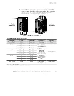
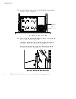
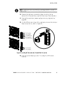
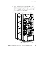
On the UPS rear panel, plug in the supplied communication terminal
block connectors as shown in Figure 25.
3-Pin Connector
2-Pin Connector
2-Pin Connector
2-Pin Connector
2-Pin with Jumper
2-Pin Connector
2-Pin with Jumper
Figure 25. Installing the Communication Terminal Block Connectors
19.
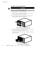
Continue to the following section, “Installing the UPS Internal
Batteries.”
Содержание Powerware BladeUPS
Страница 1: ...Powerware BladeUPS 12 kVA User s Guide ...
Страница 8: ...TABLE OF CONTENTS EATON Powerware BladeUPS 12 kVA User s Guide S 164201649 Rev 3 www powerware com iv ...
Страница 108: ...COMMUNICATION EATON Powerware BladeUPS 12 kVA User s Guide S 164201649 Rev 3 www powerware com 100 ...
Страница 132: ...TROUBLESHOOTING EATON Powerware BladeUPS 12 kVA User s Guide S 164201649 Rev 3 www powerware com 124 ...
Страница 136: ...WARRANTY EATON Powerware BladeUPS 12 kVA User s Guide S 164201649 Rev 3 www powerware com 128 ...
Страница 137: ......
Страница 138: ... 1642016493 164201649 3 ...

