background image

INSTALLATION

EATON 

Powerware

®

 BladeUPS

®

 (12 kVA) User's Guide  

S

  164201649 Rev 3

 www.powerware.com

48

Standalone UPS Installation

NOTE  

Do not make unauthorized changes to the UPS; otherwise, damage may occur to

your equipment and void your warranty.

The BladeUPS models require a dedicated branch circuit that meets the
following requirements:

S

50A (BladeUPS 12) or 30A (BladeUPS 12i) circuit with overcurrent
protection

S

Three-phase, 4-wire plus ground, 208Y/120V nominal (BladeUPS 12)
or 400Y/230V nominal, 380–415 Vac acceptable (BladeUPS 12i)

S

50/60 Hz

S

The breaker must be wall-mounted and be readily accessible to the
operator

To install the UPS:

1.

Switch off utility power to the distribution point where the UPS will
be connected. Be absolutely sure there is no power.

2.

Verify that all circuit breakers are in the OFF (O) position.

NOTE  

The load connector breaker controls the load connector only, not the output power

cord.

3.

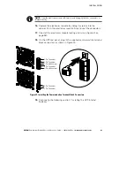
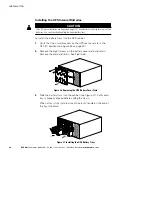
If you are installing power management software, connect your
computer to the UPS communication port or optional X-Slot card
(see page 89). For the communication port, use the supplied serial
cable.

4.

If your rack has conductors for grounding or bonding of ungrounded
metal parts, connect the ground cable (not included) to the ground
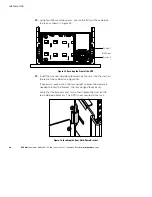
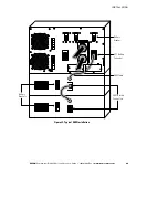
bonding screw. See Figure 32 for the location of the ground
bonding screw.

5.

If an emergency power-off (disconnect) switch is required by local
codes, see “Remote Emergency Power-off” on page 95 to install
the REPO switch before powering on the UPS.

6.

Continue to “Standalone UPS Initial Startup” on page 66.

Содержание Powerware BladeUPS

Страница 1: ...Powerware BladeUPS 12 kVA User s Guide ...

Страница 2: ...dian Interference Causing Equipment Regulations ICES 003 Cet appareil numérique de la classe A respecte toutes les exigences du Reglement sur le matériel brouilleur du Canada EN 62040 2 Some configurations are classified under EN 62040 2 as Class A UPS for Unrestricted Sales Distribution For these configurations the following applies WARNING This is a Class A UPS Product In a domestic environment ...

Страница 3: ...for use within certain voltage limits 93 68 EEC Amending Directive 73 23 EEC 89 336 EEC Council Directive relating to electromagnetic compatibility 92 31 EEC Amending Directive 89 336 EEC relating to EMC The EC Declaration of Conformity is available upon request for products with a CE mark For copies of the EC Declaration of Conformity contact Eaton Power Quality Oy Koskelontie 13 FIN 02920 Espoo ...

Страница 4: ...ional information such as important operating and maintenance instructions This symbol indicates that you should not discard the UPS or the UPS batteries in the trash This product contains sealed lead acid batteries and must be disposed of properly For more information contact your local recycling reuse or hazardous waste center This symbol indicates that you should not discard waste electrical or...

Страница 5: ...Setup 34 Checking the UPS Accessories 34 Rack Setup for the UPS 35 Installing the UPS Internal Batteries 42 EBM Installation 44 Standalone UPS Installation 48 Parallel UPS Installation 50 Multiple Parallel UPS Installation 50 Single Parallel Ready UPS Installation 56 UPS Installation into an Existing Parallel System 60 Standalone UPS Initial Startup 66 Parallel System Initial Startup 68 4 Operatio...

Страница 6: ...ow Alarm Level 88 5 Communication 89 Installing Communication Options and Control Terminals 90 Communication Options 91 DB 9 Communication Port 92 X Slot Cards 93 Control Terminals 94 Remote Emergency Power off 95 Relay Output Contacts 96 Programmable Signal Inputs 97 Parallel Communication 98 Mode Transfers 98 Redundant Signal Wiring 98 Auto Identification 99 Metering 99 6 UPS Maintenance 101 UPS...

Страница 7: ...UPS 12 kVA User s Guide S 164201649 Rev 3 www powerware com iii 7 Specifications 113 8 Troubleshooting 119 Typical Alarms and Conditions 119 Silencing the Alarm 123 Service and Support 123 9 Warranty 125 One Year Limited Warranty Global 125 ...

Страница 8: ...TABLE OF CONTENTS EATON Powerware BladeUPS 12 kVA User s Guide S 164201649 Rev 3 www powerware com iv ...

Страница 9: ...pect it and power quality can be erratic These power problems have the potential to corrupt critical data destroy unsaved work sessions and damage hardware causing hours of lost productivity and expensive repairs With the BladeUPS you can safely eliminate the effects of power disturbances and guard the integrity of your equipment The BladeUPS is designed for critical applications such as ultra hig...

Страница 10: ...ack S Normal operating mode that minimizes heat generation by operating at typically 96 5 efficiency The UPS filters incoming AC power and provides consistent power to your equipment without draining the battery S For utility line input that exceeds normal operating range automatic transfer to an online double conversion high frequency UPS design with pure sine wave output and power factor correct...

Страница 11: ...required input and output connections for the paralleled UPSs and has a single system rated input connection Figure 2 shows an example of a BladeUPS parallel system The BladeUPS system can be installed with Powerware remote power panels and rack mounted power distribution systems BladeUPS BladeUPS Bottom Entry Wireway BladeUPS Bar BladeUPS Figure 2 Example of a BladeUPS Parallel System ...

Страница 12: ...UPS S For consistent runtimes each BladeUPS in a parallel system should have the same number of EBMs S Mount EBMs for a parallel system in an adjacent rack to the left of the rack containing the BladeUPSs rack side panels removed S Some load equipment may require phase rotation or phase relationship coordination to ensure proper operation Review your equipment manufacturer s power requirement docu...

Страница 13: ...voltage even when the UPS is not connected to an AC supply S To reduce the risk of fire or electric shock install this UPS in a temperature and humidity controlled indoor environment free of conductive contaminants Ambient temperature must not exceed 40 C 104 F Do not operate near water or excessive humidity 95 maximum S To reduce the risk of fire connect only to a circuit provided with branch cir...

Страница 14: ...PÆNDING Alle reparationer og vedligeholdelse bør kun udføres af en AUTORISERET SERVICETEKNIKER Ingen af UPS ens indvendige dele kan repareres af brugeren ADVARSEL S Denne UPS indeholder sin egen energikilde batterier Udgangsstikket på UPS en kan endog være strømførende når UPS en ikke er koblet til en vekselstrømsforsyning S Installér denne UPS i et temperatur og fugtighedskontrolleret indendørsmi...

Страница 15: ...de apparatuur in bedrijf neemt en bewaar deze handleiding als naslagwerk GEVAAR Deze UPS bevat LEVENSGEVAARLIJKE ELEKTRISCHE SPANNING Alle reparaties en onderhoud dienen UITSLUITEND DOOR ERKEND SERVICEPERSONEEL te worden uitgevoerd Er bevinden zich GEEN ONDERDELEN in de UPS die DOOR DE GEBRUIKER kunnen worden GEREPAREERD WAARSCHUWING S Deze UPS bevat een eigen energiebron accu s De UPS uitgang kan...

Страница 16: ...eruimd Raadpleeg hiervoor uw plaatselijke voorschriften S Nooit batterijen in het vuur gooien De batterijen kunnen ontploffen Tarkeita Turvaohjeita TÄRKEITÄ TURVAOHJEITA SUOMI SÄILYTÄ NÄMÄ OHJEET Tämä käyttöohje sisältää tärkeitä ohjeita joita on noudatettava UPS virtalähteen ja akkujen asennuksen ja huollon yhteydessä Lue kaikki ohjeet ennen laitteiston käyttöä ja säilytä ohje myöhempää tarvetta ...

Страница 17: ... SÉCURITÉ IMPORTANTES CONSERVER CES INSTRUCTIONS Ce manuel comporte des instructions importantes que vous êtes invité à suivre lors de toute procédure d installation et de maintenance des batteries et de l onduleur Veuillez consulter entièrement ces instructions avant de faire fonctionner l équipement et conserver ce manuel afin de pouvoir vous y reporter ultérieurement DANGER Cet onduleur contien...

Страница 18: ...ez les précautions appropriées L entretien doit être réalisé par du personnel qualifié connaissant bien les batteries et les précautions nécessaires N autorisez aucun personnel non qualifié à manipuler les batteries S Une mise au rebut réglementaire des batteries est obligatoire Consulter les règlements en vigueur dans votre localité S Ne jamais jeter les batteries au feu L exposition aux flammes ...

Страница 19: ...rstellern geliefert werden S Um internationale Normen und Verdrahtungsvorschriften zu erfüllen dürfen die an den Ausgang dieser USV angeschlossenen Geräte zusammen einen Erdableitstrom von insgesamt 3 5 Milliampere nicht überschreiten VORSICHT S Batterien können das Risiko eines elektrischen Schlags bergen oder durch hohen Kurzschlussstrom in Brand geraten Die richtigen Vorsichtsmaßnahmen beachten...

Страница 20: ...ettuare il collegamento soltanto a un circuito dotato di una protezione da sovraccarico per il circuito derivato di max 100 ampere come stabilito dalle norme statunitensi sugli impianti elettrici National Electrical Code ANSI NFPA 70 S La protezione da sovraccarico per le uscite e l interruttore di scollegamento devono essere forniti da altri produttori S Per conformità con gli standard internazio...

Страница 21: ... for ledende forurensende stoffer Romtemperaturen må ikke overskride 40 C Den må ikke brukes i nærheten av vann eller ved meget høy luftfuktighet 95 maks S For å redusere brannfaren skal det bare kobles til et kretsløp med 100 A maksimum linjeforgrenings overbelastningsbeskyttelse i henhold til National Electrical Code ANSI NFPA 70 S Overbelastningsbeskyttelse for strømutgang og bryterkontakt skal...

Страница 22: ...ndutíveis A temperatura ambiente não deve exceder 40 C Não opere próximo a água ou em umidade excessiva máx 95 S Para reduzir o risco de incêndio conecte somente ao circuito fornecido com a proteção máxima de 100 ampères contra a sobretensão do circuito derivado de acordo com a norma ANSI NFPA 70 do National Electrical Code S A proteção contra a sobretensão de saída e o disjuntor deve ser fornecid...

Страница 23: ...не подключен к сети переменного тока S Для снижения опасности пожара или поражения электрическим током устанавливайте ИБП в закрытом помещении с контролируемыми температурой и влажностью в котором отсутствуют проводящие загрязняющие вещества Температура окружающего воздуха не должна превышать 40 С Не эксплуатируйте устройство около воды или в местах с повышенной влажностью макс 95 S Для того чтобы...

Страница 24: ...del SIE y de las baterías Por favor lea todas las instrucciones antes de poner en funcionamiento el equipo y guarde este manual para referencia en el futuro PELIGRO Este SIE contiene VOLTAJES MORTALES Todas las reparaciones y el servicio técnico deben ser efectuados SOLAMENTE POR PERSONAL DE SERVICIO TÉCNICO AUTORIZADO No hay NINGUNA PARTE QUE EL USUARIO PUEDA REPARAR dentro del SIE ADVERTENCIA S ...

Страница 25: ...pertinentes S Nunca deseche las baterías en el fuego Las baterías pueden explotar si se las expone a la llama Säkerhetsföreskrifter VIKTIGA SÄKERHETSFÖRESKRIFTER SPARA DESSA FÖRESKRIFTER Den här anvisningen innehåller viktiga instruktioner som du ska följa under installation och underhåll av UPS enheten och batterierna Läs alla instruktioner innan du använder utrustningen och spara den här anvisni...

Страница 26: ...ernationell standard och installationsföreskrifter får inte den totala utrustning som anslutits till uttagen på denna UPS enhet ha läcksström som överstiger 3 5 milliampere VIKTIGT S Batterierna kan innebära en risk för elektrisk stöt eller brännskada från kortsluten starkström Iakttag lämpliga försiktighetsåtgärder Service ska utföras av utbildad servicepersonal med kunskap om batterierna och nöd...

Страница 27: ...amaged during shipment keep the shipping cartons and packing materials for the carrier or place of purchase and file a claim for shipping damage If you discover damage after acceptance file a claim for concealed damage To file a claim for shipping damage or concealed damage 1 File with the carrier within 15 days of receipt of the equipment 2 Send a copy of the damage claim within 15 days to your s...

Страница 28: ...e lift the sleeve for ease of removal 2 Use care when moving and opening the cartons Leave the components packaged until ready to install Do not install the batteries until after the cabinet is installed in the rack 3 Discard or recycle the packaging in a responsible manner or store it for future use Follow these guidelines when locating the cabinet after unpacking S Place the cabinet in a protect...

Страница 29: ... BladeUPS models in a parallel configuration require a dedicated branch circuit that meets the following requirements S Circuit with overcurrent protection depending on parallel configuration Table 1 BladeUPS Overcurrent Protection Number of UPSs in Parallel System BladeUPS 12 BladeUPS 12i 2 100A 63A 3 150A 75A 4 200A 100A 5 225A 125A 6 N 1 System 225A 160A S Three phase 4 wire plus ground 208Y 12...

Страница 30: ...til it snaps into place 4 Verify that the keys lock and unlock the door 5 Optional The rack door may be flipped to allow it to open from the opposite side To flip the door Remove the hinge pins then remove the door Move the hinges to the opposite side of the rack Reorient the door and hang it on the hinges replace the hinge pins Reverse the door handle mounting NOTE The handle uses gravity to oper...

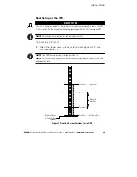
Страница 31: ...ls For example for a rack containing six UPSs and a bottom wireway plan to mount the bottom of the rails at the following marks see Figure 3 7 13 19 25 31 37 7 Figure 3 Recommended Rail Locations Example Configuration NOTE Recommended rail locations are for example only Adjust the locations as needed for your system s configuration Allow for hole spacing and numbering see Figure 3 For guidelines f...

Страница 32: ...he parallel system input and output wiring 1 Remove the four screws on the wireway access cover and retain Remove the cover and retain See Figure 4 Figure 4 Removing the Wireway Access Cover Bottom Entry Shown 2 If your rack is designed for bottom entry but you need to provide top entry wiring skip to Step 7 on page 26 Otherwise continue to Step 3 ...

Страница 33: ... top cover and retain Slide the cover back and off the wireway and retain See Figure 5 Ferrite Assembly mounted Figure 5 Removing the Wireway Top Cover Bottom Entry Shown 4 Remove the six screws on the conduit landing plate and retain Remove the plate and retain See Figure 6 Figure 6 Removing the Conduit Landing Plate Bottom Entry Shown ...

Страница 34: ...nduit landing plate 6 Skip to Step 8 7 Top entry wiring in a bottom entry rack only Use a Greenlee punch to provide one or more holes in the top of the wireway Install one or more holes in the center rear of the top of the rack See Figure 7 NOTE Verify that top entry wiring in a bottom entry rack does not interfere with access areas for the fans connectors breakers or X Slot cards on any BladeUPS ...

Страница 35: ...e 2 BladeUPS Bar Wiring Specifications BladeUPS Bar Terminal Block Terminal Position BladeUPS Bar Wire Function Terminal Wire Size Rating Tightening Torque Output 1 Output A Phase 1 Out 13 3 mm2 6 AWG to 177 mm2 350 kcmil NOTE Wire gauge depends on overcurrent protection rating required see Table 1 on page 21 Reference the NEC NFPA 70 for wire sizing 31 1 Nm 275 lb in 2 Output B Phase 2 Out 3 Outp...

Страница 36: ... and round mounting holes The rail assemblies adjust to mount in 48 cm 19 inch racks with front to rear rail distances from 61 to 76 cm 24 to 30 inches deep Checking the EBM Accessories Verify that the following items are included with the EBM S EBM front cover S Mounting brackets and fasteners if not already installed 2 mounting brackets 4 6 32 flat head screws S Rails and fasteners 2 sliding rai...

Страница 37: ...blies and adjust the rail size for the depth of your rack see Figure 9 Rear Front Rail Assembly Assembly Wing Nuts Figure 9 Adjusting the Rail Depth 2 Select the proper holes in the rail for positioning the EBM and other cabinets in the rack Place the first rail for the first EBM at the bottom using positions 1 and 6 for the front hex head screws If you are installing additional rails place the ne...

Страница 38: ...w powerware com 30 Position 1 Position 6 Position 10 Position 15 First Rail Second Rail Figure 10 Front Rail Screw Positions for the EBM 3 Secure the rail to the front of the rack with two hex head screws see Figure 11 Front Rail Hex Head Screws Figure 11 Securing the Front Rail ...

Страница 39: ...ear of the rack see Figure 12 and Figure 13 The bottom rail uses positions 2 and 4 for the rear hex head screws If you are installing additional rails place the next rail 7 holes above the last installed screw Position 2 Position 4 Position 11 Position 13 First Rail Second Rail Figure 12 Rear Rail Screw Positions for the EBM Clip Nuts Figure 13 Securing the Rear Rail ...

Страница 40: ...ble surface with the front of the EBM facing toward you 8 If the mounting brackets are not already installed align the two mounting brackets with the screw holes on the side of the EBM and secure with the supplied 6 32 flat head screws see Figure 14 9 Attach the EBM front cover Align the pins on the rear of the front cover with the openings in the EBM Push the cover firmly into place See Figure 14...

Страница 41: ...Screws Figure 15 Securing the EBM Mounting Brackets 12 Attach the rear hold down brackets to the rail and slide the brackets into the slots on the EBM rear panel see Figure 16 Rear Hold Down Bracket Figure 16 Securing the Back of the EBM 13 Verify that the brackets are seated firmly then tighten the wing nuts on the rear hold down brackets The EBM is now secured in the rack 14 Continue to the foll...

Страница 42: ... two position connectors 2 two position connectors with jumpers 1 three position connector S Software Suite CD S This user s guide S Mounting brackets and fasteners if not already installed 2 mounting brackets 8 6 32 flat head screws S Rails and fasteners 2 sliding rail assemblies left and right 2 rear hold down brackets 16 M5 machine screws 8 M5 clip nuts for racks with round holes 8 M5 cage nuts...

Страница 43: ...unting rails are required for each individual cabinet To install the UPS rail kit 1 Select the proper holes in the rack for positioning the UPS in the rack see Figure 17 NOTE The UPS takes up position 1 through position 12 NOTE Verify that the hole patterns on the rails and mounting brackets align with the hole pattern on the rack Position 1 Position 9 Mounting Bracket Top of Rail Position 12 Posi...

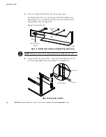
Страница 44: ...e rail and finger tighten only See Figure 18 Repeat for the other rail M6 Hex Nuts Front Rear Rear Hold Down Bracket Figure 18 Installing the Rail Hardware Right Rail Assembly Shown NOTE Verify that the holes in the rail align properly with the hole pattern in the rack 3 Using two M5 machine screws attach the rail to the front of the rack and finger tighten only see Figure 17 and Figure 19 Positio...

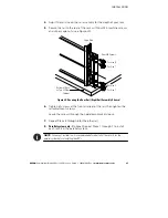
Страница 45: ... Top of Other Cabinet Rear M5 Screws Cage Nuts Figure 20 Securing the Rear Rail Right Rail Assembly Shown 6 Tighten all screws at the front and rear of the rail then tighten the rail adjustment screws Leave the screws through the hold down brackets loose 7 Repeat Steps 3 through 6 for the other rail 8 Parallel system only Optional Repeat Steps 1 through 7 to install each rail kit in the parallel s...

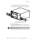
Страница 46: ...UPS facing toward you 10 Remove the electronics module and set it aside see Figure 21 Remove the electronics module locking screw at the top left of the electronics module and retain Grasp the ring handle at the middle of the module and pull the module slowly out of the cabinet Pull firmly to unseat the connectors Use two hands to support the module NOTE Treat the electronics module with care to a...

Страница 47: ...the supplied 6 32 flat head screws see Figure 22 6 32 Flat Head Screws Mounting Bracket Figure 22 Installing the UPS Mounting Brackets 12 Slide the UPS into the rack 13 Parallel or parallel ready system only If you are installing other X Slot cards besides the Powerware Hot Sync CAN Bridge Card skip to Step 16 NOTE Leaving the UPS unattached allows you to adjust the UPS position in the rack for an...

Страница 48: ... Securing the Front of the UPS 15 Insert the two rear hold down brackets on the rails into the slots on the rear of the cabinet see Figure 24 If necessary push out on the rack upright to allow the clearance needed to insert the bracket The rack upright flexes easily Verify that the brackets seat firmly then tighten the nuts on the rear hold down brackets The UPS is now secured in the rack Figure 2...

Страница 49: ...electronics module firmly to seat the connectors 17 Reinstall the electronics module locking screw see Figure 21 on page 38 18 On the UPS rear panel plug in the supplied communication terminal block connectors as shown in Figure 25 3 Pin Connector 2 Pin Connector 2 Pin Connector 2 Pin Connector 2 Pin with Jumper 2 Pin Connector 2 Pin with Jumper Figure 25 Installing the Communication Terminal Bloc...

Страница 50: ...the UPS cabinet 1 Verify that the circuit breakers on the UPS rear panel are in the OFF O position see Figure 32 on page 49 2 Remove the eight screws on the battery cover plate and retain Remove the plate and retain See Figure 26 Figure 26 Removing the UPS Battery Cover Plate 3 Slide the battery trays into the cabinet see Figure 27 Verify each tray is properly aligned before sliding the tray in Wh...

Страница 51: ...p the LCD cable in front of the electronics module Push the top of the front cover firmly into place and then push the bottom firmly into place LCD Cable Figure 28 Installing the UPS Front Cover 6 Parallel system only Repeat the steps starting at the beginning of this chapter page 19 for each UPS to be paralleled 7 If you are installing an optional EBM continue to the following section EBM Install...

Страница 52: ... To install the optional EBM s for a UPS 1 Verify that all battery circuit breakers are in the OFF O position see Figure 29 2 Plug the EBM cable s into the battery connector s as shown in Figure 29 Up to four EBMs may be connected to the UPS 3 Parallel system only Repeat Steps 1 and 2 for each UPS with EBM s See Figure 30 on page 46 and Figure 31 on page 47 for examples of EBM connections in a par...

Страница 53: ...ION EATON Powerware BladeUPS 12 kVA User s Guide S 164201649 Rev 3 www powerware com 45 Battery Breakers EBM Battery Connectors EBM Cable Battery Breaker UPS Battery Connector Figure 29 Typical EBM Installation ...

Страница 54: ...N Powerware BladeUPS 12 kVA User s Guide S 164201649 Rev 3 www powerware com 46 Figure 30 Example EBM Installations in Parallel Systems NOTE Figure 30 shows two systems using optional 0 9m 3 ft battery extension cables ...

Страница 55: ... Powerware BladeUPS 12 kVA User s Guide S 164201649 Rev 3 www powerware com 47 Figure 31 Example EBM Installation in a Large Parallel System NOTE Figure 31 shows a system using optional 0 9m 3 ft battery extension cables ...

Страница 56: ...he distribution point where the UPS will be connected Be absolutely sure there is no power 2 Verify that all circuit breakers are in the OFF O position NOTE The load connector breaker controls the load connector only not the output power cord 3 If you are installing power management software connect your computer to the UPS communication port or optional X Slot card see page 89 For the communicati...

Страница 57: ... REPO NO Communication Port Ground Bonding Screw Extended Battery Connector X Slot Communication Bay 1 X Slot Communication Bay 2 Output Power Cord Input Power Cord Surge Protection leave installed Figure 32 BladeUPS Rear Panel Standalone UPS Shown with IEC 309 60A Output Power Cord NOTE The load connector breaker controls the load connector only not the output power cord ...

Страница 58: ...r equipment and void your warranty To install two to six UPSs in a parallel configuration 1 Verify that the UPSs to be paralleled are installed in individual rail kits in a rack containing a BladeUPS Bar 2 Switch off utility power to the distribution point where the parallel system will be connected Be absolutely sure there is no power 3 Verify that all circuit breakers are in the OFF O position N...

Страница 59: ... Remove the X Slot communication bay cover on the UPS and retain the screws 6 Set the jumper pins on the Powerware Hot Sync CAN Bridge Card according to the parallel configuration see Figure 34 S If only two UPSs are paralleled then set both cards to Pins 1 and 2 S For three or more paralleled UPSs set the cards of the first and last UPS to Pins 1 and 2 set the card for the middle UPS s to Pins 2 ...

Страница 60: ...tification on page 99 9 Install the supplied initializing jumper see Figure 35 into the CAN IN port on the first UPS UPS 1 in Figure 36 On startup the parallel system will identify the UPS with the initializing jumper as UNIT 1 Initializing Jumper Figure 35 Installing the Initializing Jumper 10 Using the supplied connectors install a CAN Bridge Card cable between each UPS as shown in Figure 36 con...

Страница 61: ...erware com 53 UPS 3 UPS 2 UPS 1 CAN Bridge Card Cable CAN CAN IN OUT Initializing Jumper Redundant Signal Cable For Parallel Use Only Standalone Parallel For Parallel Use Only Standalone Parallel Standalone Parallel remove Figure 36 Typical CAN Bridge Card and Redundant Signal Wiring ...

Страница 62: ...nstalling power management software connect your computer to the UPS communication port or optional X Slot card see page 89 For the communication port use the supplied serial cable NOTE You may install one ConnectUPS X Web SNMP Card per UPS or one card per parallel system Installing one card per UPS provides communication with each UPS Installing one card per parallel system provides detection of ...

Страница 63: ...UPS to the BladeUPS Bar in the rack as shown in Figure 37 Gently loop and twist the parallel input cords as shown to minimize stress on the cords The loop and twist for each cord may vary depending on configuration and strain relief 19 Continue to Parallel System Initial Startup on page 68 Figure 37 Connecting UPSs to the BladeUPS Bar Bottom Entry Shown ...

Страница 64: ...o install one UPS in a parallel ready configuration 1 Verify that the UPS is installed in a rail kit in a rack containing a BladeUPS Bar 2 Switch off utility power to the distribution point where the parallel ready UPS system will be connected Be absolutely sure there is no power 3 Verify that all circuit breakers are in the OFF O position NOTE The load connector breaker controls the load connecto...

Страница 65: ... Slot Communication Bay 2 see Figure 32 on page 49 leaving the X Slot Communication Bay 1 available for other types of X Slot cards 5 Remove the X Slot communication bay cover on the UPS and retain the screws 6 Set the jumper pins on the Powerware Hot Sync CAN Bridge Card as shown in Figure 39 Jumper J7 Pins 1 and 2 Figure 39 Setting the CAN Bridge Card Jumper J7 Side View ...

Страница 66: ...lling the Initializing Jumper 9 Tighten the screws securing the Powerware Hot Sync CAN Bridge Card in its X Slot communication bay 10 If you are installing power management software connect your computer to the UPS communication port or optional X Slot card see page 89 For the communication port use the supplied serial cable NOTE You may install one ConnectUPS X Web SNMP Card per UPS or one card p...

Страница 67: ...ation of the ground bonding screw 13 You can install an optional REPO circuit that will shut down the entire parallel ready system using a single switch See Remote Emergency Power off on page 95 to install the REPO switch before powering on the parallel ready system 14 Connect the parallel input cord from the UPS to the BladeUPS Bar in the rack as shown in Figure 37 on page 55 Gently loop and twis...

Страница 68: ...or disconnecting the load If you prefer to remove input power to install additional UPSs see Parallel System Shutdown on page 85 To install one to five UPSs into an existing parallel or parallel ready configuration 1 Verify that the UPSs to be paralleled are installed in individual rail kits in a rack containing a BladeUPS Bar 2 For each additional UPS being installed verify that all circuit break...

Страница 69: ... Remove the X Slot communication bay cover on the UPS and retain the screws 5 Set the jumper pins on the Powerware Hot Sync CAN Bridge Card according to the parallel configuration see Figure 42 S If only two UPSs are paralleled then set both cards to Pins 1 and 2 S For three or more paralleled UPSs set the cards of the first and last UPS to Pins 1 and 2 set the card for the middle UPS s to Pins 2 ...

Страница 70: ...ties to each UPS in the system based on the order in which their CAN Bridge Cards are wired in Steps 9 and 10 For more information see Auto Identification on page 99 9 Verify that the supplied initializing jumper is installed in the CAN IN port on the first UPS UPS 1 in Figure 43 On startup the parallel system will identify the UPS with the initializing jumper as UNIT 1 10 Using the supplied conne...

Страница 71: ...erware com 63 UPS 3 UPS 2 UPS 1 CAN Bridge Card Cable CAN CAN IN OUT Initializing Jumper Redundant Signal Cable For Parallel Use Only Standalone Parallel For Parallel Use Only Standalone Parallel Standalone Parallel remove Figure 43 Typical CAN Bridge Card and Redundant Signal Wiring ...

Страница 72: ...installing power management software connect your computer to the UPS communication port or optional X Slot card see page 89 For the communication port use the supplied serial cable NOTE You may install one ConnectUPS X Web SNMP Card per UPS or one card per parallel system Installing one card per UPS provides communication with each UPS Installing one card per parallel system provides detection of...

Страница 73: ...he parallel input cords as shown to minimize stress on the cords The loop and twist for each cord may vary depending on configuration and strain relief 20 Continue to Parallel System Initial Startup on page 68 If you installed the additional UPS s without shutting down the parallel system perform the steps in Parallel System Initial Startup on the additional UPS s only Figure 44 Connecting UPSs to...

Страница 74: ...ity power where the UPS is connected 6 Remove the breaker ties from the circuit breakers 7 Switch the UPS input circuit breaker to the ON position 8 Wait for the UPS front panel display to illuminate The indicator flashes on the UPS 9 Check the UPS front panel display for active alarms or notices other than Batteries Disconnected Resolve any active alarms before continuing See Troubleshooting on p...

Страница 75: ...e now energized If the indicator is flashing do not proceed until all alarms are clear Check the UPS status from the front panel to view the active alarms Correct the alarms and restart if necessary The UPS should be in Normal mode By default Normal mode operates on the High Efficiency setting see Normal Mode on page 76 16 To energize a load connected through the load connector switch the load con...

Страница 76: ...s do not exceed the parallel system capacity to prevent an overload alarm 1 Verify that all UPS circuit breakers are in the OFF O position NOTE The load connector breaker controls the load connector only not the output power cord 2 Switch on utility power where the UPS is connected 3 Remove the breaker ties from the circuit breakers 4 Switch the UPS input circuit breaker on each UPS to the ON posi...

Страница 77: ...ss and hold the button for three seconds until the UPS stops beeping Verify that the indicator illuminates solid on each UPS indicating that the UPS is operating normally and any loads not connected through the load connector are now energized If the indicator on any UPS is flashing do not proceed until all alarms are clear Check the UPS status from the front panel to view the active alarms Correc...

Страница 78: ...S installed to be part of a future parallel system set the Parallel Operation Settings Parallel Operation Mode to Capacity Mode to prevent unnecessary alarms 17 If you installed an optional REPO test the REPO function Activate the external REPO switch Verify the status change on the UPS display Deactivate the external REPO switch and restart the UPS NOTE The batteries charge to 80 capacity in less...

Страница 79: ...cal LCD with backlight It provides useful information about the UPS itself load status events measurements and settings see Figure 45 Power On Indicator green On Battery Indicator yellow Bypass Indicator yellow Alarm Indicator red Control Buttons for the LCD Menu Options Figure 45 BladeUPS Control Panel The Mimic screen shows the internal components of the UPS and a real time display of the operat...

Страница 80: ...shooting on page 119 for additional information Changing the Language Press and hold the first button on the left for approximately five seconds to select the language menu This action is possible from any LCD menu screen Display Functions As the default or after 15 minutes of inactivity the LCD displays the selectable startup screen The default is the Eaton Powerware logo and can be changed to th...

Страница 81: ...otal Output Voltage L N and L L Current Frequency Power kW Power kVA Power pf Battery Voltage Current Runtime Input Voltage L N and L L Current Frequency Load Receptacle Voltage Current Power kW Power kVA Frequency Control Go to Bypass Mode Transfers the UPS system to internal Bypass mode When this command is active the option changes to Go to Normal Mode Start Battery Test Initiates a battery tes...

Страница 82: ...3 4 or X Slot 2 1 2 3 4 Setup On Battery Summary Alarm On Bypass UPS OK custom empty Alarm 1 empty X Slots 1 or 2 1 UPS OK 2 On Bypass 3 Summary Alarm 4 On Battery Signal Inputs Signal X Slot 1 X Slot 2 INPUT 1 INPUT 2 signal inputs Logic 0 1 For more information see Programmable Signal Inputs on page 97 empty 1 Serial Port Config Port X Slot 1 X Slot 2 Serv Speed 19200 9600 2400 1200 19200 Parall...

Страница 83: ...tery Tests on page 87 Enabled automatically runs the battery test once a month Power Strategy High Efficiency Standard The Standard setting is limited to 60 minutes when selected through the front panel See the following section Operating Modes High Efficiency Start Screen Eaton Powerware logo Mimic screen see Figure 46 on page 71 Eaton Powerware logo User Password Enabled Disabled If Enabled is s...

Страница 84: ... 71 shows the UPS front panel indicators and controls Normal Mode During Normal mode the indicator illuminates solid and the UPS is powered from the utility The UPS monitors and charges the batteries as needed and provides filtered power protection to your equipment By default the BladeUPS operates on a High Efficiency setting that minimizes heat contribution to the rack environment The system byp...

Страница 85: ...or estimated runtimes When utility power is restored after the UPS shuts down the UPS automatically restarts Bypass Mode In the event of a UPS overload or internal failure the UPS transfers your equipment to utility power Battery mode is not available and your equipment is not protected however the utility power continues to be passively filtered by the UPS The indicator illuminates The UPS transf...

Страница 86: ...PS circuit breakers are in the OFF O position NOTE The load connector breaker controls the load connector only not the output power 2 Verify that the UPS power cord is plugged in 3 Switch on utility power where the UPS is connected 4 Switch the UPS input circuit breaker to the ON position 5 Wait for the UPS front panel display to illuminate The indicator flashes on the UPS 6 Check the UPS front pa...

Страница 87: ...firm the selection Press and hold the button for three seconds until the UPS stops beeping Verify that the indicator illuminates solid indicating that the UPS is operating normally and any loads not connected through the Load Connector are now energized If the indicator is flashing do not proceed until all alarms are clear Check the UPS status from the front panel to view the active alarms Correct...

Страница 88: ...or flashes on each UPS 7 Check each UPS front panel display for active alarms or notices other than Batteries Disconnected Resolve any active alarms before continuing See Troubleshooting on page 119 8 Switch all UPS battery circuit breakers to the ON position 9 If optional EBMs are installed switch all EBM battery circuit breakers to the ON position 10 Verify that the Batteries Disconnected alarm ...

Страница 89: ...es on the High Efficiency setting see Normal Mode on page 76 13 To energize loads connected through the Load Connectors switch all load connector circuit breakers to the ON position 14 On any UPS press the ESC button until the Eaton Powerware logo appears Starting the UPS on Internal Bypass NOTE Starting the UPS on internal bypass leaves the load unprotected To start a standalone UPS on internal b...

Страница 90: ... the indicator is flashing do not proceed until all alarms are clear Check the UPS status from the front panel to view the active alarms Correct the alarms and restart if necessary 10 Press any button on the front panel display to activate the menu options Select CONTROL and GO TO BYPASS MODE The indicator illuminates solid and the indicator flashes indicating the UPS is operating in Bypass mode T...

Страница 91: ...e menu options Select TURN UPS ON OFF TURN UPS OFF and press the button 3 Confirm the selection Press and hold the button for three seconds until the UPS stops beeping The output relays open the UPS transfers to Standby mode and the indicator turns off 4 Switch the UPS battery circuit breaker to the OFF O position 5 If optional EBMs are installed switch all EBM battery circuit breakers to the OFF ...

Страница 92: ...three seconds until the UPS stops beeping The output relays open the UPS transfers to Standby mode and the indicator turns off 4 Switch the UPS battery circuit breaker to the OFF O position 5 If optional EBMs are installed switch all EBM battery circuit breakers to the OFF O position 6 Switch the UPS input circuit breaker to the OFF O position 7 Disconnect the redundant signal cable s from the UPS...

Страница 93: ...press the button 3 Confirm the selection Press and hold the button for three seconds until the UPS stops beeping The UPS removes power to the parallel UPS system output The output relays open the UPSs transfer to Standby mode and the indicators turn off 4 Switch the UPS battery circuit breaker to the OFF O position 5 If optional EBMs are installed switch all EBM battery circuit breakers to the OFF...

Страница 94: ...TROL and GO TO NORMAL MODE Alternatively standalone UPS only Press any button to activate the menu options then select TURN UPS ON OFF TURN UPS ON and OK to confirm Setting Power Strategy To set the power strategy 1 Press any button to activate the menu options then select SETTINGS USER SETTINGS and POWER STRATEGY 2 Select HIGH EFFICIENCY or STANDARD and OK to confirm NOTE Time in the Standard pow...

Страница 95: ... configuration All UPS and EBM Cabinets Number of EBMs UPS only 0 default UPS 1 EBM 1 UPS 2 EBMs 2 UPS 3 EBMs 3 UPS 4 EBMs 4 3 Press the button to save the setting 4 Press the ESC button until the Eaton Powerware logo appears Running Automatic Battery Tests Battery tests rely on backfeeding the utility using the utility as a load Some sites may choose to disable battery testing if their source is ...

Страница 96: ...ing times for a parallel system with additional EBMs installed see Table 5 Table 5 Suggested Battery Low Alarm Level Settings Warning Time in Minutes Number of EBMs Installed Battery Low Alarm Level User Setting 20 Load 50 Load 100 Load 2 1 1 783 1 821 1 854 2 1 776 1 811 1 831 3 1 772 1 798 1 818 4 1 768 1 781 1 805 3 1 1 805 1 848 1 891 2 1 793 1 833 1 859 3 1 787 1 820 1 843 4 1 781 1 803 1 831...

Страница 97: ...able signal inputs S Parallel communication Figure 47 shows the location of the communication options and control terminals on the UPS DB 9 Communication Port REPO normally closed REPO normally open Signal Input 2 Signal Input 1 X Slot Communication Bay 2 X Slot Communication Bay 1 Relay Output Contacts Standalone Parallel Redundant Signal Wiring For Parallel Use Only Figure 47 Communication Optio...

Страница 98: ...d control terminals 1 Install the appropriate X Slot card and or necessary cable s see Figure 47 and Figure 48 Figure 48 Installing Communication Cables 2 Connect the cables to the appropriate location See Communication Options on page 91 or Control Terminals on page 94 for detailed information 3 Route and tie the cable s out of the way 4 Continue to Operation on page 71 to start up the UPS ...

Страница 99: ...to the following table Independent Multiplexed X Slot 1 X Slot 2 DB 9 Communication Port Any X Slot card Any X Slot card except the Powerware Modem Card Not in use Any X Slot card Powerware Relay Interface Card Powerware Hot Sync CAN Bridge Card Available Any X Slot card Not in use Available NOTE You can configure relays signal inputs and the serial port baud rate through the front panel menus see...

Страница 100: ...he UPS for detailed information on the status of the power environment If a power emergency occurs the software initiates the saving of all data and an orderly shutdown of the equipment The cable pins are identified in Figure 49 and the pin functions are described in Table 6 See Figure 47 on page 89 for the communication port location 3 8 7 9 1 6 2 4 5 Figure 49 Communication Port Table 6 Communic...

Страница 101: ...idity temperature smoke alarm and security information S Relay Interface Card has isolated dry contact Form C relay outputs for UPS status Utility failure Low battery UPS alarm OK or On bypass S Modbus Card allows you to continuously and reliably monitor the UPSs in your Building Management System BMS S Industrial Relay Card IRC is used to indicate the operating status of the UPS system using the ...

Страница 102: ... resistors Polarity Polarity 2 1 Polarity Polarity 2 1 2 1 2 1 Signal Input 1 programmable Signal Input 2 programmable REPO Normally Open REPO Normally Closed Normally Open Normally Closed 1 2 Common 3 Relay Output UPS Connectors see Figure 47 on page 89 Polarity Polarity 2 1 Redundant Signal Wiring For Parallel Use Only Polarity Polarity 2 1 Standalone Parallel Figure 51 External Control Terminal...

Страница 103: ...uired The REPO switch must have a minimum rating of 24 Vdc and 20 mA and be a dedicated latching type switch not tied into any other circuit The REPO signal must remain active for at least 250 ms for proper operation S To ensure the UPS stops supplying power to the load during any mode of operation the input power must be disconnected from the UPS when the emergency power off function is activated...

Страница 104: ...ted REPO command The REPO wiring of a standalone UPS can be connected with the REPO wiring of a parallel system if the same sense NO or NC contacts are used Be sure to match the polarity for the contacts NOTE To restart the UPS reconnect the REPO connector pins and turn on the UPS manually The pins must be shorted to keep the UPS running Maximum resistance is 10 ohm NOTE Always test the REPO funct...

Страница 105: ... discharge of batteries is supported on OFF If active the UPS output turns off regardless of the mode of operation Auxiliary power communication and rectifier battery charger remain functional Restart is initiated immediately when this signal is inactive force bypass If active the UPS is forced to static bypass operation regardless of the bypass status ext battery breaker If active the UPS knows t...

Страница 106: ...BMs to maximize runtime In a parallel system configured for redundancy the UPSs use a distributed bypass and the following alarms cause an individual UPS to shut down instead of transferring to Bypass mode S Failure of the fan fuse temperature sensor or power supply S Inverter AC under voltage S Battery current limit S DC link under voltage S Battery over voltage Redundant Signal Wiring BladeUPS 1...

Страница 107: ...nsate for the missing UPS until logic power to all the UPSs is cycled For example if you remove UNIT 2 and rewire UNIT 3 s CAN IN port to UNIT 1 s CAN OUT port UNIT 3 will not re identify itself as UNIT 2 until logic power is cycled The CAN Bridge Cards for UNIT 1 and UNIT 3 continue to function normally without the need to re identify Metering The Output and Load Receptacle meter readings differ ...

Страница 108: ...COMMUNICATION EATON Powerware BladeUPS 12 kVA User s Guide S 164201649 Rev 3 www powerware com 100 ...

Страница 109: ... The batteries in the UPS are rated for a 3 5 year service life The length of service life varies depending on the frequency of usage and ambient temperature Batteries used beyond expected service life will often have severely reduced runtimes Replace batteries at least every 5 years to keep units running at peak efficiency Storing the UPS and Batteries If you store the UPS for a long period recha...

Страница 110: ...etal objects 2 Use tools with insulated handles 3 Do not lay tools or metal parts on top of batteries 4 Wear rubber gloves and boots S When replacing batteries replace with the same type and number of batteries or battery packs Contact your service representative to order new batteries S Proper disposal of batteries is required Refer to your local codes for disposal requirements S Never dispose of...

Страница 111: ...M cable from the UPS If additional EBMs are installed unplug the EBM cable from the battery connector on each EBM 3 If not already installed install the supplied mounting brackets on the new EBM 4 Replace the EBM See Recycling the Used Battery or UPS on page 112 for proper disposal 5 Plug the new EBM into the UPS as shown in Figure 29 on page 45 For additional EBMs plug the EBM cable into the batt...

Страница 112: ...attery trays in the UPS cabinet 1 Verify that the battery circuit breaker is in the OFF O position see Figure 32 on page 49 2 Remove the UPS front cover and set it aside see Figure 52 Grasp the fingergrips on both sides of the cover and pull the cover forward firmly Unplug the LCD cable connecting the back of the control panel to the electronics module LCD Cable Figure 52 Removing the UPS Front Co...

Страница 113: ...N Powerware BladeUPS 12 kVA User s Guide S 164201649 Rev 3 www powerware com 105 3 Remove the eight screws on the battery cover plate and retain Remove the plate See Figure 53 Figure 53 Removing the UPS Battery Cover Plate ...

Страница 114: ... when you pull them out of the UPS 4 Untuck the plastic handle at the end of a battery tray Pull the handle firmly to remove the tray Use both hands to support the tray as it leaves the UPS cabinet Repeat for each battery tray See Recycling the Used Battery or UPS on page 112 for proper disposal 5 Slide the new battery trays into the cabinet see Figure 54 Verify each tray is properly aligned befor...

Страница 115: ...over into the connector on the electronics module Use care to gently loop the LCD cable in front of the electronics module Push the top of the front cover firmly into place and then push the bottom firmly into place NOTE Reconnecting the control panel to the electronics module automatically transfers the UPS to Normal mode 8 Verify that there are no alarms indicated on the control panel LCD Cable ...

Страница 116: ...th at least 10 load applied to the UPS To test new batteries 1 Plug the UPS into a power outlet for 48 hours to charge the battery 2 Press any button to activate the menu options 3 Select CONTROL then START BATTERY TEST During the battery test the front panel displays Battery Test Pending A failed battery test initiates a Battery Test Failed alarm To cancel a battery test in progress 1 Press any b...

Страница 117: ...Transfer the UPS to Bypass mode Parallel for capacity configurations only Transfer the UPS to Bypass mode The CAN bus remains energized Parallel for redundancy configurations only No mode transfer is necessary If the UPS is operating in a parallel for redundancy configuration when its electronics module is removed the load automatically transfers to the remaining UPSs The CAN bus remains energized...

Страница 118: ...electronics module and retain Grasp the ring handle at the middle of the module and pull the module slowly out of the cabinet Pull firmly to unseat the connectors Use two hands to support the module NOTE Treat the electronics module with care to avoid damaging the fans connectors or internal circuitry Electronics Module Locking Screw Ring Handle LCD Cable Figure 56 Removing the UPS Front Cover and...

Страница 119: ...only Reconnect the redundant signal cable s 7 Replace the UPS front cover see Figure 57 Plug the LCD cable from the control panel on the front cover into the connector on the electronics module Use care to gently loop the LCD cable in front of the electronics module Push the top of the front cover firmly into place and then push the bottom firmly into place 8 Verify that there are no alarms indica...

Страница 120: ...discard the UPS or the UPS batteries in the trash This product contains sealed lead acid batteries and must be disposed of properly For more information contact your local recycling reuse or hazardous waste center CAUTION Do not discard waste electrical or electronic equipment WEEE in the trash For proper disposal contact your local recycling reuse or hazardous waste center Updating the UPS Firmwa...

Страница 121: ...12 kW at 208V BladeUPS 12i 12 kVA or 12 kW at 400V EBM Model Number BladeEBM BladeUPS Bar Model Number BladeUPS Bar 60 For up to 6 UPSs Derated for line cord and nominal line voltage Cord Model Number Description Input Plug Type Length UPSCord12UL 12 kW UL input IEC 309 60A 3 7m 12 ft UPSCord12ULR 12 kW UL input output IEC 309 60A 1 8 1 2m 6 4 ft UPSCordPUL 12 kW UL parallel Anderson 0 5m 1 5 ft U...

Страница 122: ...ry tray 20 kg 44 lb Electronics module 19 5 kg 43 lb 77 kg 170 lb Table 10 BladeUPS Bar 60 Dimensions WxDxH 140 x 113 x 1827 mm 5 5 x 4 4 x 71 9 Weight BladeUPS Bar 19 kg 42 lb Wireway Enclosure 20 kg 45 lb Total Weight 39 kg 87 lb UPS Connections Up to 6 Rack Placement Bottom wireway fits into the bottom 6U of standard rack space Top wireway fits into the top 6U of standard rack space Table 11 Bl...

Страница 123: ...Hz 50 60 Hz Frequency Range 45 65 Hz 45 65 Hz Default Frequency Auto detected Auto detected Rated Input Current 36A 24A Connections IEC 309 60A power cord IEC 309 32A power cord For paralleling a single Anderson input output cord connects to the BladeUPS Bar see Table 8 on page 113 Noise Filtering MOVs and common mode line filter Input Power Factor High Efficiency setting load dependent Standard s...

Страница 124: ...Anderson connector Short Circuit Capability Battery Mode 84A 300 ms 44A 300 ms Short Circuit Capability Normal Mode Limited by 50A input breaker Limited by 30A input breaker Nominal Output Frequency 50 60 Hz auto detection Normal mode 50 or 60 Hz Battery mode Output Frequency Variation Synchronized Normal mode 0 1 when not synchronized with source Battery mode Output Overload 100 110 load transfer...

Страница 125: ...32 F to 77 F Transit Temperature 25 C to 55 C 13 F to 131 F Relative Humidity Operating 5 95 noncondensing Non operating 5 95 relative humidity 38 7 C 101 7 F Maximum wet bulb temperature with no cosmetic damage Operating Altitude Up to 1 000 meters 3 300 ft above sea level up to 2 000 meters 6 600 ft with 1 derating per 100 meters 330 ft Transit Altitude Up to 15 000 meters 49 000 ft above sea le...

Страница 126: ...acid Monitoring Advanced monitoring for earlier failure detection and warning Charging in minutes 8 10 times the discharge time NOTE Charging times are approximate and are to 80 usable capacity at nominal line voltage after full load discharge Table 16 Battery Runtimes in Minutes Model UPS Internal Batteries 1 EBM 2 EBMs 3 EBMs 4 EBMs BladeUPS 12 4 8 12 20 27 34 BladeUPS 12i 4 8 12 20 27 34 NOTE B...

Страница 127: ...he menu options 2 Press the button until EVENT LOG displays 3 Press the button to display the list of alarms and conditions Alarm or Condition Possible Cause Action On Battery LED is on 1 short beep every 5 seconds A utility failure has occurred and the UPS is in Battery mode The UPS is powering the equipment with battery power Prepare your equipment for shutdown Battery Low LED is on Continuous b...

Страница 128: ...under voltage bypass over or under frequency or bypass unavailable Battery Connection LED is on 1 beep every 3 seconds The UPS does not recognize the internal batteries If the condition persists contact your service representative Two or more battery trays are disconnected Verify that all battery trays are fully seated and locked in place If the condition persists contact your service representati...

Страница 129: ... The batteries or electronics module is being replaced Complete the replacement procedure before starting the UPS The REPO switch is active or the REPO connector is missing Reset the REPO switch and restart the UPS Verify that the REPO connector is present The UPS does not turn off The batteries or electronics module is being replaced Complete the replacement procedure before shutting down the UPS...

Страница 130: ...tatus from the UPS front panel If all UPSs appear in the list check the redundant signal wiring see page 54 Set the system to internal Bypass mode see page 101 If the condition persists contact your service representative Abnormal output voltage at startup The system is not configured as parallel Verify the CAN wiring see page 52 Verify the line cord is installed properly Shut down the UPS where t...

Страница 131: ...All other countries Call your local service representative Please have the following information ready when you call for service S Model number S Serial number S Firmware version number S Date of failure or problem S Symptoms of failure or problem S Customer return address and contact information If repair is required you will be given a Returned Material Authorization RMA Number This number must ...

Страница 132: ...TROUBLESHOOTING EATON Powerware BladeUPS 12 kVA User s Guide S 164201649 Rev 3 www powerware com 124 ...

Страница 133: ...pany If the Warranted Item is to be replaced by Company and the End User supplies a credit card number or purchase order for the value of the replacement Product Company will use commercially reasonable business efforts to ship via standard ground shipment and at no cost to the End User the replacement Warranted Item to the End User within one 1 business day after Company receives notice of the wa...

Страница 134: ...SPECIFICALLY DOES NOT WARRANT SOFTWARE SUCH AS LINUX THAT WAS CREATED USING AN OPEN SOURCE MODEL OR IS DISTRIBUTED PURSUANT TO AN OPEN SOURCE LICENSE THIS WARRANTY IS THE SOLE AND EXCLUSIVE WARRANTY OFFERED BY COMPANY WITH RESPECT TO THE PRODUCTS AND SERVICES AND EXCEPT FOR SUCH FOREGOING WARRANTY COMPANY DISCLAIMS ALL OTHER WARRANTIES INCLUDING BUT NOT LIMITED TO ANY IMPLIED WARRANTIES OF MERCHAN...

Страница 135: ...STS NOT RELATED TO WARRANTY The End User shall be invoiced for and shall pay for all services not expressly provided for by the terms of this Warranty including without limitation site calls involving an inspection that determines no corrective maintenance is required Any costs for replacement equipment installation materials freight charges travel expenses or labor of Company representatives outs...

Страница 136: ...WARRANTY EATON Powerware BladeUPS 12 kVA User s Guide S 164201649 Rev 3 www powerware com 128 ...

Страница 137: ......

Страница 138: ... 1642016493 164201649 3 ...

Отзывы: