INSTALLATION
EATON
Powerware
®
BladeUPS
®
(12 kVA) User's Guide
S
164201649 Rev 3
www.powerware.com
27
8.
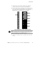
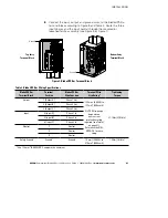
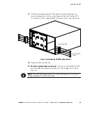
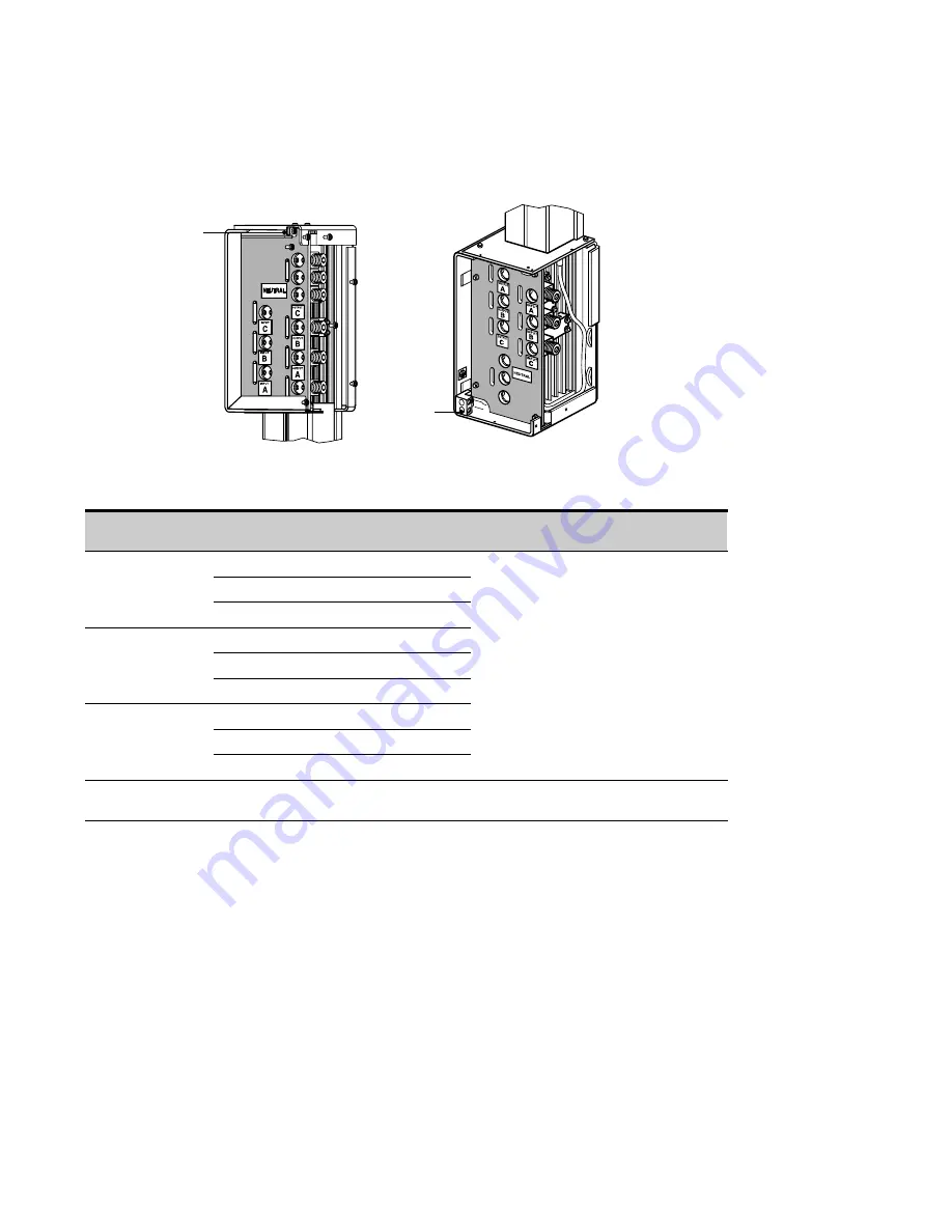
Connect the input, output, and ground wires to the BladeUPS Bar
terminal block according to Figure 8 and Table 2. Route the three
input phases and the input neutral through the mounted or
loosened ferrite assembly (see Figure 5 or Figure 7).
Ground
Ground
Top Entry
Terminal Block
Bottom Entry
Terminal Block
Figure 8. BladeUPS Bar Terminal Block
Table 2. BladeUPS Bar Wiring Specifications
BladeUPS Bar
Terminal Block
Terminal
Position
BladeUPS Bar
Wire Function
Terminal Wire
Size Rating*
Tightening
Torque
Output
1 [Output A]
Phase 1 Out
13.3 mm
2
(6 AWG) to
177 mm
2
(350 kcmil)
NOTE
Wire gauge
depends on
overcurrent
protection rating
required (see Table 1
on page 21).
Reference the NEC,
NFPA 70, for wire
sizing.
31.1 Nm (275 lb in)
2 [Output B]
Phase 2 Out
3 [Output C]
Phase 3 Out
Input
4 [Input A]
Phase 1 In
5 [Input B]
Phase 2 In
6 [Input C]
Phase 3 In
Neutral
7
Neutral
8
Neutral
9
Neutral
Safety Ground
Ground
Ground
18 mm
2
(4 AWG) to
215 mm
2
(400 kcmil)
1.8 Nm (16 lb in)
* Use 13.3 mm
2
(6 AWG) 90
_
C copper wire minimum.
Содержание Powerware BladeUPS
Страница 1: ...Powerware BladeUPS 12 kVA User s Guide ...
Страница 8: ...TABLE OF CONTENTS EATON Powerware BladeUPS 12 kVA User s Guide S 164201649 Rev 3 www powerware com iv ...
Страница 108: ...COMMUNICATION EATON Powerware BladeUPS 12 kVA User s Guide S 164201649 Rev 3 www powerware com 100 ...
Страница 132: ...TROUBLESHOOTING EATON Powerware BladeUPS 12 kVA User s Guide S 164201649 Rev 3 www powerware com 124 ...
Страница 136: ...WARRANTY EATON Powerware BladeUPS 12 kVA User s Guide S 164201649 Rev 3 www powerware com 128 ...
Страница 137: ......
Страница 138: ... 1642016493 164201649 3 ...

