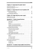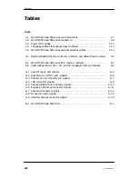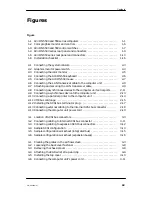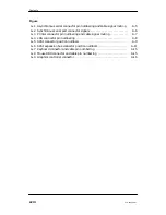
Contents
xvi
014–002250–01
Figure
5–1 Internal drive slots
. . . . . . . . . . . . . . . . . . . . . . . . . . . . . . . . . . . . . . . . . . . . . . . .
5–2 Removing the drive SCSI bus and power cables
. . . . . . . . . . . . . . . . . . . . . . .
5–3 Releasing the drive mounting lock
. . . . . . . . . . . . . . . . . . . . . . . . . . . . . . . . . . .
5–4 Removing a drive assembly from the computer unit
. . . . . . . . . . . . . . . . . . .
5–5 Attaching the mounting hardware
. . . . . . . . . . . . . . . . . . . . . . . . . . . . . . . . . . .
5–6 Removing a filler panel from the computer chassis front drive cage
. . . . .
5–7 Aligning the drive assembly for installation
. . . . . . . . . . . . . . . . . . . . . . . . . .
5–8 Installing a drive assembly in the computer unit
. . . . . . . . . . . . . . . . . . . . .
5–9 Securing the drive with the mounting lock
. . . . . . . . . . . . . . . . . . . . . . . . . . .
5–10 SCSI bus internal ribbon cable and drive power cables
. . . . . . . . . . . . . . . .
5–11 Installing the SCSI bus ribbon cable and drive power cable
. . . . . . . . . . . .
6–1 Location of memory module connector banks
. . . . . . . . . . . . . . . . . . . . . . . . .
6–2 Numbering scheme for memory module connectors
. . . . . . . . . . . . . . . . . . .
6–3 SIMM configurations
. . . . . . . . . . . . . . . . . . . . . . . . . . . . . . . . . . . . . . . . . . . . . . .
6–4 Releasing the memory module locking tabs
. . . . . . . . . . . . . . . . . . . . . . . . . . .
6–5 Removing a memory module
. . . . . . . . . . . . . . . . . . . . . . . . . . . . . . . . . . . . . . . .
6–6 Inserting the memory module in the connector
. . . . . . . . . . . . . . . . . . . . . . .
6–7 Securing a memory module in its connector with locking tabs
. . . . . . . . . .
7–1
AViiON 5500 and 550 series expansion CPU board
. . . . . . . . . . . . . . . . . . . .
7–2
Removing the CPU expansion board screws
. . . . . . . . . . . . . . . . . . . . . . . . . .
7–3
Installing a CPU expansion board
. . . . . . . . . . . . . . . . . . . . . . . . . . . . . . . . . . .
7–4
Securing CPU expansion boards to the system board
. . . . . . . . . . . . . . . . . .
7–5
Location of external I/O option slots
. . . . . . . . . . . . . . . . . . . . . . . . . . . . . . . . .
7–6
Releasing the I/O expansion board from the computer bulkhead
. . . . . . . .
7–7
Removing an I/O expansion board
. . . . . . . . . . . . . . . . . . . . . . . . . . . . . . . . . . .
7–8
Removing expansion SCSI and LAN connector filler plates
. . . . . . . . . . . .
7–9
Positioning logic boards to determine singled–ended or differential bus
configurations on a SCSI expansion controller
. . . . . . . . . . . . . . . . . . .
7–10 Removing a logic board from a SCSI expansion board
. . . . . . . . . . . . . . . . .
7–11 Installing logic boards on an expansion SCSI board
. . . . . . . . . . . . . . . . . . .
7–12 Installing an expansion I/O board
. . . . . . . . . . . . . . . . . . . . . . . . . . . . . . . . . . .
7–13 Securing an I/O expansion board
. . . . . . . . . . . . . . . . . . . . . . . . . . . . . . . . . . . .
7–14 Securing the I/O expansion board to the computer unit bulkhead
. . . . . . .
7–15 Location of the AViiON 550 series graphics board (8–bit or 24–bit)
. . . . .
7–16 Releasing the graphics controller from the computer bulkhead
. . . . . . . . .
7–17 Removing the 8–bit graphics controller
. . . . . . . . . . . . . . . . . . . . . . . . . . . . . .
7–18 Removing the 24–bit graphics controller
. . . . . . . . . . . . . . . . . . . . . . . . . . . . .
7–19 Removing graphics controller filler plates
. . . . . . . . . . . . . . . . . . . . . . . . . . . .
7–20 Installing the 8–bit graphics controller
. . . . . . . . . . . . . . . . . . . . . . . . . . . . . .
7–21 Installing the 24–bit graphics controller
. . . . . . . . . . . . . . . . . . . . . . . . . . . . .
7–22 Securing the I/O expansion board to the computer unit bulkhead
. . . . . . .
Содержание AViiON 550 Series
Страница 2: ......
Страница 6: ......
Страница 12: ...Joining our users group x 014 002250 01 ...
Страница 86: ...Opening and closing the computer unit 4 12 014 002250 01 ...
Страница 96: ...Installing a drive assembly 5 10 014 002250 01 ...
Страница 188: ......
Страница 191: ......

