Integrated I/O connectors and signals
A-6
014–002250–01
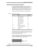
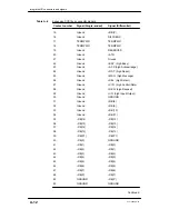
Synchronous serial port connector
Synchronous devices connect through the 25-pin female
D–connector (DB25) located on the back of the computer unit,
labeled
SYNC
.
Figure A–2 shows the pin numbers for the synchronous
communications connector; Table A–2 lists the signals.
14
13
1
25
female connector
Figure A–2
Synchronous serial port connector signals
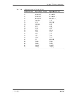
Table A–2
Synchronous (SYNC) port signals
Pin
Signal
Direction
1
Chassis Ground
n/a
2
Transmit Data (TxD)
Out
3
Receive Data (RCD)
In
4
Request to Send (RTS)
Out
5
Clear to Send (CTS)
In
6
Data Set Ready (DSR)
In
7
Signal Ground (SG)
Both
8
Data Carrier Detect (DCD)
In
15
Transmit Timing (Tx Clock)
In
17
Receive Timing (RCV Clock)
In
20
Data Terminal Ready (DTR)
Out
22
Ring Indicator (RI)
In
24
Terminal Signal Timing (SC)
Out
Содержание AViiON 550 Series
Страница 2: ......
Страница 6: ......
Страница 12: ...Joining our users group x 014 002250 01 ...
Страница 86: ...Opening and closing the computer unit 4 12 014 002250 01 ...
Страница 96: ...Installing a drive assembly 5 10 014 002250 01 ...
Страница 188: ......
Страница 191: ......


