Integrated I/O connectors and signals
A-9
014–002250–01
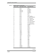
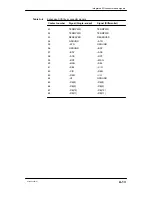
Table A–4 specifies the signals for the LAN connector.
Table A–4
LAN connector signals
Pin
Signal
Circuit
1
Ground
CI–S (control in shield)
2
Col
CI–A (control in A)
3
Tr
DO–A (data out A)
4
Ground
DI–S (data in shield)
5
R
DI–A (data in A)
6
Ground
VC (voltage common)
7
No Connection
CO–A (control out A)
8
Ground
CO–S (control out shield)
9
Collision –
CI–B (control in B)
10
Transmit –
DO–B (data in B)
11
Ground
DO–S (data out shield)
12
Receive –
DI–B (data in B)
13
+12 V
VP (voltage plus)
14
Ground
VS (voltage shield)
15
No Connection
CO–B (control out B)
Shell
Ground
PG (protective ground)
Integrated SCSI–2 bus connector
An external connector for the integrated SCSI bus is located on the
rear panel of every AViiON 5500 and 550 series computer. Some
systems may include as many as four expansion SCSI buses; see the
next section for information about a SCSI expansion bus connector.
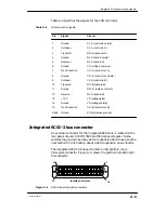
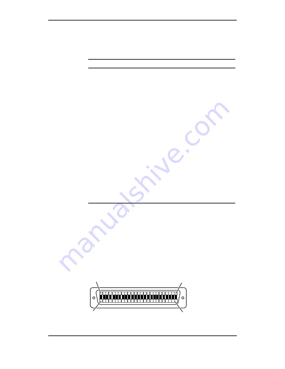
The integrated SCSI–2 bus port contains a 50–position, male
P&S–style connector. Figure A–5 shows the position numbering for
the connector.
25
female connector
50
1
26
Figure A–5
SCSI connector position numbers
Содержание AViiON 550 Series
Страница 2: ......
Страница 6: ......
Страница 12: ...Joining our users group x 014 002250 01 ...
Страница 86: ...Opening and closing the computer unit 4 12 014 002250 01 ...
Страница 96: ...Installing a drive assembly 5 10 014 002250 01 ...
Страница 188: ......
Страница 191: ......


