Preparing a replacement system board
8-7
014–002250–01
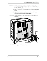
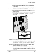
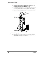
4. Align the pins of the PROM component with the holes in the system
board socket. Insert the PROM component into the socket, as shown
in Figure 8–8.
System board
PROM component
Figure 8–8
Installing the System ID PROM component
5. Gently push on one side and then the other side to seat the PROM
component in the socket.
"
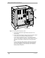
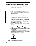
Next, verify that configuration jumpers on the system board are
positioned correctly for your configuration, as described below.
Figure 8–9 illustrates the system board layout; it indicates both the
location and the default configuration of the system board jumpers.
Labels identifying each jumper number appear below the jumpers
on the system board.
Содержание AViiON 550 Series
Страница 2: ......
Страница 6: ......
Страница 12: ...Joining our users group x 014 002250 01 ...
Страница 86: ...Opening and closing the computer unit 4 12 014 002250 01 ...
Страница 96: ...Installing a drive assembly 5 10 014 002250 01 ...
Страница 188: ......
Страница 191: ......


