Rules for installing memory modules
6-3
014–002250–01
Rules for installing memory modules
When you install memory modules, you must follow the
configuration and installation rules in this section.
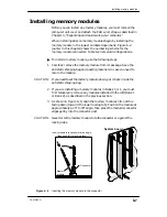
There are three banks of four SIMM connectors. The connectors are
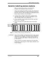
grouped in clusters of three (one cluster for each bank). Figure 6–2
shows the numbering scheme and labeling for AViiON 5500 and 550
series memory connectors on the system board.
D
You install memory modules in banks of four, starting with the
rightmost connector in each 3–connector group (Bank 0). Never
leave a connector empty in a four–SIMM bank.
D
All four connectors in a bank must be filled with the same SIMM
type (4–, 16–, or 32–Mbyte).
D
Only the third bank of connectors (Bank 2) can hold 32–Mbyte
SIMMs.
Bank 0 = black
Bank 1 = grey
Bank 2 = white
2
2
1
0
0
0
2
2
1
1
1
0
Figure 6–2
Numbering scheme for memory module connectors
IMPORTANT:
When removing modules in configurations with more than one bank
installed, you must temporarily remove the module installed to the
left of the one you are replacing. For example, to remove a Bank 0
module, you must remove the Bank 1 module to the left of the one
you are replacing.
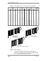
Table 6–2 lists each valid memory configuration for AViiON 5500
and 550 series systems. Figure 6–3 shows modules installed in each
of the three banks.
Содержание AViiON 550 Series
Страница 2: ......
Страница 6: ......
Страница 12: ...Joining our users group x 014 002250 01 ...
Страница 86: ...Opening and closing the computer unit 4 12 014 002250 01 ...
Страница 96: ...Installing a drive assembly 5 10 014 002250 01 ...
Страница 188: ......
Страница 191: ......

