Installing memory modules
6-8
014–002250–01
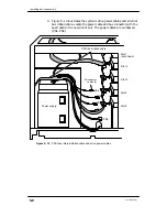
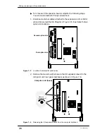
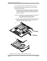
4. Gently push on the module until it is perpendicular to the system
board, as shown in Figure 6–6.
You hear and feel a click as each connector tab locks into place.
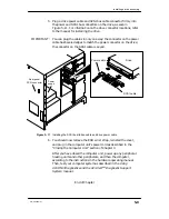
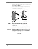
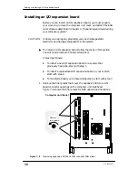
5. Be sure the locking tabs on both sides of the SIMM connector are
securely in place, as seen in Figure 6–7.
SIMM
SIMM connector
Post
Locking tab
Figure 6–7
Securing a memory module in its connector with locking tabs
6. Repeat steps 3 through 5 to install or reinstall any remaining
memory module(s).
7. If you are not replacing any other CRUs, reinstall the cover as
described in the section,“Closing the computer unit” in Chapter 4.
IMPORTANT:
Your system automatically sizes the amount of memory at each
powerup. Examine powerup messages if you have increased or
reduced system memory configuration.
End of Chapter
Содержание AViiON 550 Series
Страница 2: ......
Страница 6: ......
Страница 12: ...Joining our users group x 014 002250 01 ...
Страница 86: ...Opening and closing the computer unit 4 12 014 002250 01 ...
Страница 96: ...Installing a drive assembly 5 10 014 002250 01 ...
Страница 188: ......
Страница 191: ......

