■
INST:
Height = 0.0625, Justify = Center, Insertion point = above LOC
■
FAMILY:
Insertion point = anywhere
Once you place the FAMILY attribute, the FAMILY code dialog box displays. The
Family value generally matches the TAG1 %F value. This value is only used when
naming the block.
10
Click OK.
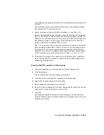
Notice that the FAMILY and TAG1%F codes display in the
Component type: Schematic Parent or Stand-alone dialog box
above the Insert Attribute button. These values should both
be PS.
11
Click Back to Main Menu.
Add wire connection points
1
Click Wire Connection.
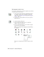
You can define wire connection points and terminal text for
the library symbol. The Terminal style/configuration dialog
box displays.
2
Select terminal style 1=Screw.
This terminal style inserts both the graphic to represent the
screw and the wire connection points.
You have to determine which direction the wire will attach to
the component. In this exercise, wire connection attributes
are inserted at the left, bottom, and right side of the symbol.
1226 | Chapter 19 Advanced Productivity
Содержание 22505-051400-9000 - AutoCAD Electrical 2008
Страница 1: ...AutoCAD Electrical 2008 User s Guide February 20 2007 ...
Страница 4: ...1 2 3 4 5 6 7 8 9 10 ...
Страница 79: ...command is invoked AutoCAD Electrical automatically inserts this block at 0 0 Create a new drawing 67 ...
Страница 106: ...94 ...
Страница 228: ...216 ...
Страница 242: ...HP W TERM_ VDC SPECIAL SPACINGFACTOR 0 5 HP WA D TERM_ 02 230 Chapter 5 PLC ...
Страница 294: ...282 ...
Страница 564: ...552 ...
Страница 698: ...686 ...
Страница 740: ...728 ...
Страница 814: ...802 ...
Страница 1032: ...1020 ...
Страница 1134: ...1122 ...
Страница 1168: ...1156 ...
Страница 1177: ...Insert P ID Component Overview of pneumatic tools 1165 ...
Страница 1198: ...1186 ...
Страница 1269: ...AutoCAD Electrical Command In this chapter AutoCAD Electrical Commands 20 1257 ...
Страница 1304: ...Z zip utility 82 1292 Index ...

