


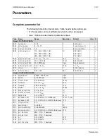


1-60
ACH550-UH User’s Manual
Application macros
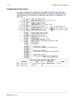
Floating Point macro
This application macro is for applications where speed reference needs to be
controlled through digital inputs (DI5 & DI6). By activating digital input 5, the speed
reference increases, by activating digital input 6, the speed reference decreases. If
both digital inputs are active or inactive, the reference does not change.
Note:
When constant speed 1 is activated using digital input 3 (DI3), the reference
speed is the value of parameter 1202. The value remains as the reference speed
when digital input 3 is deactivated.
Parameters Changed Relative to HVAC Default
Parameter
Value
Parameter
Value
9902
APPLIC
MACRO
10 (
FLOATING
PNT
)
3416
SIGNAL
3
MIN
-200.0%
1103
REF
1
SEL
7 (
DI
5
U
, 6
D
)
3417
SIGNAL
3
MAX
200.0%
1401
RELAY
OUTPUT
1
7 (
STARTED
)
3419
OUTPUT
3
UNIT
4 (%)
1601
RUN
ENABLE
2 (
DI
2)
3420
OUTPUT
3
MIN
-200.0%
3415
SIGNAL
3
PARAM
0105 (
TORQUE
)
3421
OUTPUT
3
MAX
200.0%
1 SCR
2 AI1
3 AGND
4 10V
5 AI2
6 AGND
7 AO1
8 AO2
9 AGND
10 24V
11 GND
12 DCOM
13 DI1
14 DI2
15 DI3
16 DI4
17 DI5
18 DI6
19 RO1C
20 RO1A
21 RO1B
22 RO2C
23 RO2A
24 RO2B
25 RO3C
26 RO3A
27 RO3B
X1
mA
mA
Not configured
Reference voltage 10 VDC
Output frequency:
0(4)…20 mA
Start/Stop:
Activate to start drive
Run permissive:
Deactivate to stop drive (P 1601)
Constant (Preset) speed 1
(P 1202)
Safety interlock 1:
Deactivate to stop drive (P 1608)
Reference up:
Activate to increase reference (P 1103)
Relay output 1 (P 1401)
Default operation:
Started
=>19 connected to 21
Relay output 2 (P 1402)
Default operation:
Running
=>22 connected to 24
Relay output 3 (P 1403)
Default operation:
Fault (-1)
=>25 connected to 27
Output current:
0(4)…20 mA
Reference down:
Activate to decrease reference (P 1103)
Analog input circuit common
Not configured
Analog output circuit common
Auxiliary voltage 24 VDC
Auxiliary voltage output common
Digital input common for all
Signal cable shield (screen)
Analog input circuit common
(Fault => 25 connected to 26)
J1
AI1: 0(4)
…
20 mA
AI2: 0(4)
…
20 mA
ON
J1 Jumper Settings
ON
ON
12
J1
Содержание ACH550-BCR
Страница 4: ...iv Manual contents ...
Страница 5: ...ACH550 UH User s Manual 1 1 ACH550 UH HVAC Drives 1 550 HP User s Manual 2016 ABB All Rights Reserved ...
Страница 6: ......
Страница 12: ...1 8 ACH550 UH User s Manual Table of contents ...
Страница 36: ...1 32 ACH550 UH User s Manual Installation ...
Страница 70: ...1 66 ACH550 UH User s Manual Application macros ...
Страница 335: ...ACH550 UH User s Manual 1 331 Technical data ...
Страница 348: ......
Страница 382: ...2 36 ACH550 E Clipse Bypass User s Manual Start up ...
Страница 398: ...2 52 ACH550 E Clipse Bypass User s Manual Bypass functions overview ...
Страница 406: ...2 60 ACH550 E Clipse Bypass User s Manual Application macros ...
Страница 544: ...2 198 ACH550 E Clipse Bypass User s Manual Embedded fieldbus ...
Страница 584: ...2 238 ACH550 E Clipse Bypass User s Manual Diagnostics ...
Страница 608: ......
Страница 612: ...3 6 ACH550 UH User s Manual Table of contents ...
Страница 622: ...3 16 ACH550 PCR PDR User s Manual Installation ...
Страница 641: ......


