


ACH550-UH User’s Manual
1-317
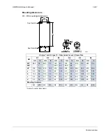
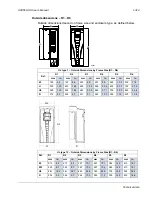
Technical data
Note:
For safety reasons the fault relay signals a “fault” when the ACH550 is
powered down.
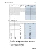
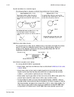
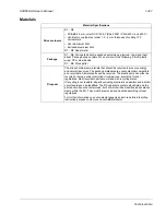
X1
Drive Control Terminal Description
1
SCR
Terminal for signal cable screen. (Connected internally to chassis ground.)
2
AI1
Analog input channel 1, programmable. Default
2
= external reference. Resolution
0.1%, accuracy ±1%.
J1:AI1 OFF: 0(2)…10 V (R
i
= 312 k
)
J1:AI1 ON: 0(4)…20 mA (R
i
= 100
)
3
AGND
Analog input circuit common (connected internally to chassis gnd. through 1 M
).
4
+10 V
Potentiometer reference source: 10 V ±2%, max. 10 mA (1k
< R < 10k
).
5
AI2
Analog input channel 2, programmable. Default
2
= PID feedback. Resolution 0.1%,
accuracy ±1%.
J1:AI2 OFF: 0(2)…10 V (R
i
= 312 k
)
J1:AI2 ON: 0(4)…20 mA (R
i
= 100
)
6
AGND
Analog input circuit common (connected internally to chassis gnd. through 1 M
).
7
AO1
Analog output, programmable. Default
2
= frequency. 0…20 mA (load < 500
).
Accuracy ±3% full scale.
8
AO2
Analog output, programmable. Default
2
= current. 0…20 mA (load < 500
).
Accuracy ±3% full scale.
9
AGND
Analog output circuit common (connected internally to chassis gnd. through 1 M
).
10 +24V
Auxiliary voltage output 24 VDC / 250 mA (reference to GND), short circuit
protected.
11 GND
Auxiliary voltage output common (connected internally as floating).
12 DCOM Digital input common. To activate a digital input, there must be
10 V
(or
-10 V) between that input and DCOM. The 24 V may be provided by the
ACH550 (X1-10) or by an external 12…24 V source of either polarity.
13 DI1
Digital input 1, programmable. Default
2
= start/stop.
14 DI2
Digital input 2, programmable. Default
2
= not configured.
15 DI3
Digital input 3, programmable. Default
2
= constant (preset) speed.
16 DI4
Digital input 4, programmable. Default
2
= safety interlock.
17 DI5
Digital input 5, programmable. Default
2
= not configured.
18 DI6
Digital input 6, programmable. Default
2
= not configured.
19 RO1C
Relay output 1, programmable. Default
2
= Ready
Maximum: 250 VAC / 30 VDC, 2 A
Minimum: 500 mW (12 V, 10 mA)
20 RO1A
21 RO1B
22 RO2C
Relay output 2, programmable. Default
2
= Running
Maximum: 250 VAC / 30 VDC, 2 A
Minimum: 500 mW (12 V, 10 mA)
23 RO2A
24 RO2B
25 RO3C
Relay output 3, programmable. Default
2
= Fault (-1)
Maximum: 250 VAC / 30 VDC, 2 A
Minimum: 500 mW (12 V, 10 mA)
26 RO3A
27 RO3B
Analo
g
I/O
ON
ON
1
2
or, for OFF
ON
1
2
for ON
ON
ON
ON
1
2
or, for OFF
ON
1
2
for ON
ON
Dig
it
a
l In
pu
ts
1
Re
la
y Ou
tpu
ts
Содержание ACH550-BCR
Страница 4: ...iv Manual contents ...
Страница 5: ...ACH550 UH User s Manual 1 1 ACH550 UH HVAC Drives 1 550 HP User s Manual 2016 ABB All Rights Reserved ...
Страница 6: ......
Страница 12: ...1 8 ACH550 UH User s Manual Table of contents ...
Страница 36: ...1 32 ACH550 UH User s Manual Installation ...
Страница 70: ...1 66 ACH550 UH User s Manual Application macros ...
Страница 335: ...ACH550 UH User s Manual 1 331 Technical data ...
Страница 348: ......
Страница 382: ...2 36 ACH550 E Clipse Bypass User s Manual Start up ...
Страница 398: ...2 52 ACH550 E Clipse Bypass User s Manual Bypass functions overview ...
Страница 406: ...2 60 ACH550 E Clipse Bypass User s Manual Application macros ...
Страница 544: ...2 198 ACH550 E Clipse Bypass User s Manual Embedded fieldbus ...
Страница 584: ...2 238 ACH550 E Clipse Bypass User s Manual Diagnostics ...
Страница 608: ......
Страница 612: ...3 6 ACH550 UH User s Manual Table of contents ...
Страница 622: ...3 16 ACH550 PCR PDR User s Manual Installation ...
Страница 641: ......


