


Components
547
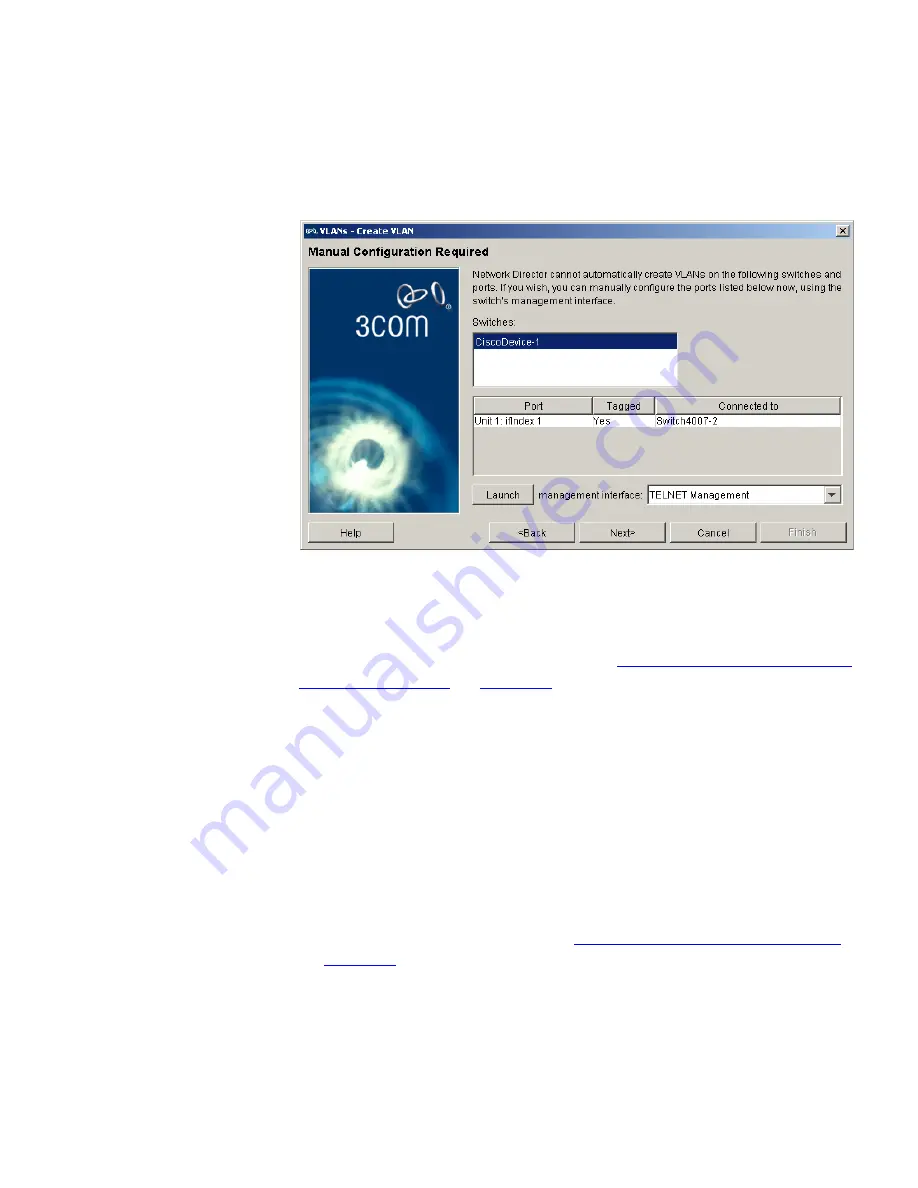
Figure 294
Manually Configuring a VLAN on Unsupported Devices
The
Switches:
list contains all the switches on which the new VLAN will
have to be manually created. The table below lists those ports that will
need to be manually added to the new VLAN on the switch currently
selected in the list and indicates whether the ports should be tagged or
untagged based on the rules explained in
“Modifying the list of selected
switches and ports”
on
page 553
.
You can either manually configure these unsupported devices at this
point in the wizard, or wait until 3Com Network Director has
automatically created the VLAN on all the supported devices before
manually configuring the unsupported devices. If you choose to manually
configure the unsupported devices at this point in the wizard, you can
use the
Launch
button to launch the Telnet or Web management
interface for the selected device.
Adding an IP routing interface
The next wizard stage allows you to specify a new IP routing interface(s)
to be used with the new VLAN. See
“Communication between VLANs”
on
page 504
for more information.
Содержание 3C15500 - Network Director - PC
Страница 1: ...http www 3com com Part No DUA1550 0AAA01 Published May 2004 3Com Network Director User Guide 3C15500 ...
Страница 4: ......
Страница 34: ......
Страница 38: ...34 ABOUT THIS GUIDE ...
Страница 50: ...46 CHAPTER 1 GETTING STARTED ...
Страница 64: ...60 CHAPTER 2 PRODUCT ACTIVATION ...
Страница 213: ...Components 209 Figure 75 Export to Visio Dialog Box ...
Страница 220: ...216 CHAPTER 5 WORKING WITH THE MAP Figure 84 Double Clicking on a Router in the Tree ...
Страница 264: ...260 CHAPTER 6 VIEWING DEVICE DETAILS Figure 117 Security Tab for a Device ...
Страница 276: ...272 CHAPTER 6 VIEWING DEVICE DETAILS ...
Страница 322: ...318 CHAPTER 7 MONITORING THE NETWORK ...
Страница 385: ...Examples 381 Figure 189 Attach Alerts Dialog Box ...
Страница 406: ...402 CHAPTER 9 PERFORMANCE REPORTING ...
Страница 431: ...Components 427 History View dialog box Figure 210 History View Dialog Box ...
Страница 440: ...436 CHAPTER 10 RMON Host View dialog box Figure 219 Host View Dialog Box ...
Страница 476: ...472 CHAPTER 11 CREATING REPORTS ...
Страница 502: ...498 CHAPTER 12 CONFIGURING SINGLE DEVICES ...
Страница 526: ...522 CHAPTER 13 VLAN MANAGEMENT Figure 272 Options Dialog Box VLANs Tab ...
Страница 567: ...Components 563 Figure 305 Selecting the Link to the End Station on the Map ...
Страница 626: ...622 CHAPTER 14 BULK CONFIGURATION ...
Страница 684: ...680 CHAPTER 16 UPGRADING DEVICE SOFTWARE ...
Страница 814: ...810 CHAPTER 19 BACKING UP DEVICE CONFIGURATIONS ...
Страница 838: ...834 CHAPTER 20 LIVE UPDATE ...
Страница 894: ...890 APPENDIX G ADDING MAC ADDRESS VENDOR TRANSLATIONS ...