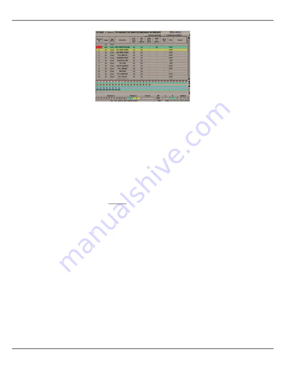
The Monitor Screen
The monitor screen display is divided
into a number of different sections
which are described below.
Screen Selection Buttons
The top section of the monitor screen
contains the main screen selection
buttons which are labelled
F1 - F6
.
The main screens are as follows:
•
F1 - Setup
•
F2 - Memories
•
F3 - Submasters
•
F4 - Cueline
•
F5 - DMX Output
•
F6 - DMX Patch
Clicking on one of these buttons, or
pressing the corresponding SCREEN
FUNCTION button, or function key on
the external keyboard, displays the
selected screen in the main data area
of the monitor screen.
Main Data Area
The centre section of the monitor
screen shows information which is
dependent on the currently selected
main screen (Setup, Memories etc.)
When the desk is in Super User Mode,
the Super User screen is displayed in
this centre section of the screen.
Channel Data Display (CDD)
The Channel Data Display (CDD)
shows the current output values of the
dimmer channels and fixture
brightness parameters.
The output values are displayed in
percentage (0-100) or DMX (0-255)
format which is determined in the
Desk
Defaults
section of
Desk Setup
.
An output value of zero is displayed as
“-” rather than “0”.
Output values of topsetted dimmer
channels or fixtures are displayed in
red text, rather than the normal black.
The initial size (height) of the CDD is
set up in
Desk Setup;
the height of the
CDD can be altered directly on the
monitor screen using the mouse.
Fade Status Bar
The Fade Status Bar displays status
information on the Submasters,
Playback X, Override, Grand Master,
Playback A/B and Auxiliaries.
The
Submasters
are shown in grey
when zero, red when fading, and green
when above zero. When the submaster
is outputting data from a different page
(overlaid), the background is orange.
The
Playback X
area shows the
Current
(green) and
Next
(yellow)
memories in the memory stack. When
a fade is taking place a red bar moves
across the whole area.
The
Override
field indicates the
position of the OVERRIDE control
(neutral = green, fast or slow = red).
If the optional upgrade kit is fitted, and
the desk is in SMPTE or MIDI Time
Mode, the
Override
field is replaced by
the
Timecode
field (see chapter 5).
The
Grand Master (GM)
field indicates
the position of the GRAND MASTER.
When Blackout is active a red flashing
“Blackout” is displayed in this field.
The
Playback A/B
fields indicate which
memories (if any) are loaded onto the
A MASTER and B MASTER faders.
The backgrounds are grey when the
master is at zero, red when fading, and
green when above zero.
The
Auxiliaries
are grey when off, red
when fading, and green when on.
Illusion 500 Manual 73-741-00 Issue 2
1 - 9
Introduction
Figure 1 - 10: Memories Screen on the Monitor
Summary of Contents for ILLUSION 500
Page 1: ...ILLUSION 500 OPERATING MANUAL ...
Page 2: ......
Page 6: ...iv Illusion 500 Manual 73 741 00 Issue 2 Contents ...
Page 40: ...3 20 Illusion 500 Manual 73 741 00 Issue 2 Setup ...
Page 121: ......


