OPERATING INSTRUCTIONS
Lattice Lightsheet 7
System Operation
ZEISS
04/2021 V_01
000000-2324-960
77
3.2.3
Lightsheet Alignment and Stage Levelling
Only necessary, if new sample/sample carrier has been inserted.
1.
Switch TL LED off.
2.
Switch on one laser light, e.g. 488 nm.
3.
Put filter to “None” position.
4.
The laser power will be set to the minimum and
cannot be changed (laser power control slider
inactivated) to avoid damage to the camera if
Filter is in “None” position.
5.
Select Light sheet, e. g. 30 x 1000 will work well
with cells. Switch off dithering.
6.
Choose camera ROI of 1000 px x 300 px.
7.
Set camera exposure time to 5 ms.
8.
Start continuous.
9.
Focus using the Ergopointer until the light sheet
becomes the thinnest possible (Fig. 61).
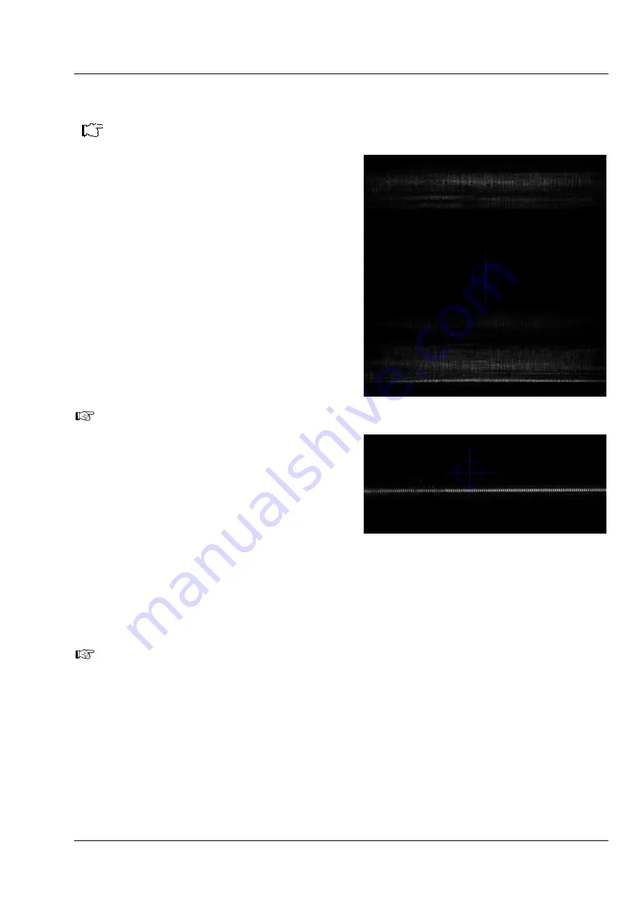
In case it was not possible to focus on the
sample with Transmitted Light there might be
two broad beam reflections be visible
originating from the lower cover glass /
immersion and upper glass surface / sample
interfaces, respectively (Fig. 60). You must
focus on the upper of the two reflected beams.
In case of doubt move z until the lower cover
glass reflex starts to appear, then move back
to the upper reflex.
Fig. 60
Lower and upper glass reflection if
not focused
Fig. 61
Reflected light (focused)
10.
Activate Center Line (Macro) (Fig. 62). A red horizontal line will appear.
11.
Move the red line over the light sheet.
12.
Move Tilt X until the light sheet is parallel to the red line.
Move Tilt Y only if the light sheet changes position in Y when Y is changed. This step can normally be
omitted.
The Tilt Y is corrected if the reflected light sheet beam does not move in Y in regard to the red line
when the stage is moved in Y direction for a longer distance
13.
You might delete the red line by pressing the keyboards
Delete
button or the
Delete
icon from the
graphics tool (red line must be actively selected).


