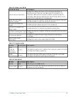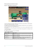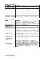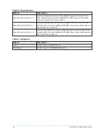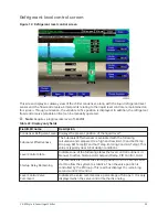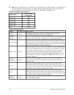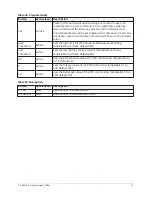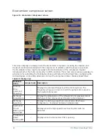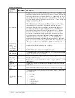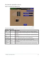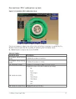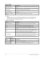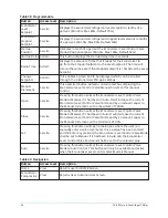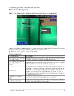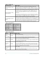
Table 26: Display only fields
Field/LED
name
Access level Description
Oil Pressure
–
Displays the pressure differential between the high side oil pressure
transducer (compressor bearing input) and the low side oil pressure
transducer (oil sump). The displayed value includes offset pressure
derived from auto-zeroing during the System Prelube. If either of
the transducers used to calculate this differential is out of range, the
display field will show XX.X.
The offset pressure is the pressure differential between the high
oil pressure (HOP) transducer and the low oil pressure (LOP)
transducer outputs during a three (3) second period beginning
ten (10) seconds into the System Prelube. During this time, the
transducers will be sensing the same pressure and their outputs
should indicate the same pressure. However, due to accuracy
tolerances in transducer design, differences can exist. Therefore
to compensate for differences between transducers and assure
differential pressure sensing accuracy, the offset pressure is
subtracted algebraically from the differential pressure. The offset
pressure calculation will not be performed if either transducer is out
of range. The offset value will be taken as 0 PSI in this instance.
Oil Pump
Drive
Command
Frequency
–
Displays the electrical frequency of the Oil Pump Drive motor. The
frequency will go up or down to match the pump motor output to
the required oil pressure.
Vane Motor
Switch (LED)
–
Illuminates when the vanes are completely closed.
Oil Return
Solenoid
(LED)
–
Illuminates when the solenoid is energized.
Pre-Rotation
Vanes
Control
Mode
Service
Indicates whether the vanes are under manual or automatic control.
Pre-Rotation
Vanes Open
(LED)
Service
Indicates whether the vanes are in the process of opening.
Pre-Rotation
Vanes Close
(LED)
Service
Indicates whether the vanes are in the process of closing.
Full Load
Amps
Service
Displays the motor current as a percentage of the Full Load Amps
(FLA) value.
43
YK-EP Style B Centrifugal Chiller
Summary of Contents for YK-EP
Page 2: ...2 YK EP Style B Centrifugal Chiller...
Page 6: ...6 YK EP Style B Centrifugal Chiller...
Page 227: ...Figure 72 Sample printout of Status 227 YK EP Style B Centrifugal Chiller...
Page 228: ...Figure 73 Sample printout of Status cont YK EP Style B Centrifugal Chiller 228...
Page 229: ...Figure 74 Sample printout of Setpoints 229 YK EP Style B Centrifugal Chiller...
Page 230: ...Figure 75 Sample printout of Setpoints cont YK EP Style B Centrifugal Chiller 230...
Page 231: ...Figure 76 Sample printout of Schedule 231 YK EP Style B Centrifugal Chiller...
Page 232: ...Figure 77 Sample printout of a Sales order YK EP Style B Centrifugal Chiller 232...
Page 233: ...Figure 78 Sample printout of a Sales order cont 233 YK EP Style B Centrifugal Chiller...
Page 234: ...Figure 79 Sample printout of History YK EP Style B Centrifugal Chiller 234...
Page 235: ...Figure 80 Sample printout of History cont 235 YK EP Style B Centrifugal Chiller...
Page 236: ...Figure 81 Sample printout of a security log report YK EP Style B Centrifugal Chiller 236...

