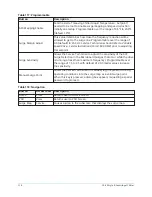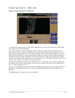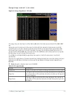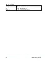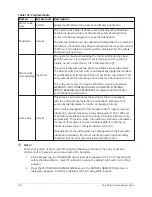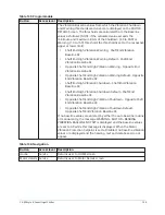
Table 130: Display only
Field/LED name
Description
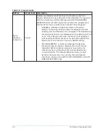
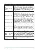
Vibration
Displays the Shaft End and Opposite End vibration values. The
vibration values are not in any particular units of measure. They are
relative values. The larger the number, the greater the magnitude
of vibration represented. When the Motor Vibration Protection
Setpoint is set to Disabled, no vibration values are displayed and the
heading, text and data boxes do not appear.
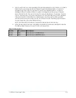
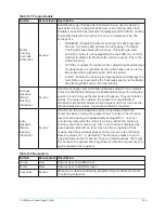
Auto Baseline Time Left
Only appears when the auto baseline routine is running. Displays
the time remaining in the 1 hour auto baseline routine.
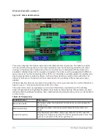
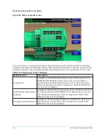
Vibration Baseline
Displays the Shaft End and Opposite End vibration values
established during the running of the auto baseline routine using
the AUTO BASELINE key or by manual entry using the MANUAL
BASELINE key. The vibration values are not in any particular units
of measure. They are relative values. The larger the number, the
greater the magnitude of vibration represented. These values also
create the High Vibration Shutdown and High Vibration Warning
thresholds as follows: (NOTE: if the calculated value exceeds the
minimum and maximum limits of the Shutdown (2.0 to 30.0) or
Warning (1.0 to 15.0) threshold, the threshold is set to the respective
upper or lower limit):
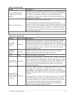
•
Shaft End High Vibration Warning - Shaft End Vibration
Baseline X2
•
Shaft End High Vibration Warning Default - Shaft End
Vibration Baseline X2
•
Opposite Shaft End High Vibration Warning - Opposite End
Vibration Baseline X2
•
Opposite Shaft End High Vibration Warning Default - Opposite
End Vibration Baseline X2
•
Shaft End High Vibration Shutdown - Shaft End Vibration
Baseline X3
•
Shaft End High Vibration Shutdown Default - Shaft End
Vibration Baseline X3
•
Opposite Shaft End High Vibration Shutdown - Opposite Shaft
End Vibration Baseline X3
•
Opposite Shaft End High Vibration Shutdown Default -
Opposite Shaft End Vibration Baseline X3
These automatically derived values can be overridden by manually
entering a threshold on the MOTOR SETPOINTS Screen using the
VIBRATION SETUP key.
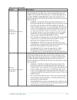
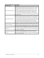
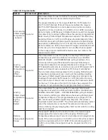
If no baseline values are entered, by either the auto baseline routine
or manual entry, the message WARNING – MOTOR – BEARING
VIBRATION BASELINE NOT SET is displayed and the baseline values
are set to X.X while this message is displayed. When the Motor
Vibration Protection Setpoint is set to Disabled, no baseline vibration
values are displayed and the heading, text and data boxes do not
appear.
YK-EP Style B Centrifugal Chiller
132
Summary of Contents for YK-EP
Page 2: ...2 YK EP Style B Centrifugal Chiller...
Page 6: ...6 YK EP Style B Centrifugal Chiller...
Page 227: ...Figure 72 Sample printout of Status 227 YK EP Style B Centrifugal Chiller...
Page 228: ...Figure 73 Sample printout of Status cont YK EP Style B Centrifugal Chiller 228...
Page 229: ...Figure 74 Sample printout of Setpoints 229 YK EP Style B Centrifugal Chiller...
Page 230: ...Figure 75 Sample printout of Setpoints cont YK EP Style B Centrifugal Chiller 230...
Page 231: ...Figure 76 Sample printout of Schedule 231 YK EP Style B Centrifugal Chiller...
Page 232: ...Figure 77 Sample printout of a Sales order YK EP Style B Centrifugal Chiller 232...
Page 233: ...Figure 78 Sample printout of a Sales order cont 233 YK EP Style B Centrifugal Chiller...
Page 234: ...Figure 79 Sample printout of History YK EP Style B Centrifugal Chiller 234...
Page 235: ...Figure 80 Sample printout of History cont 235 YK EP Style B Centrifugal Chiller...
Page 236: ...Figure 81 Sample printout of a security log report YK EP Style B Centrifugal Chiller 236...

