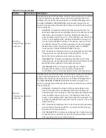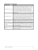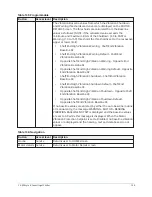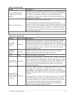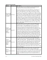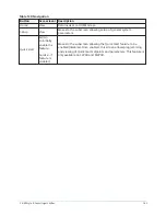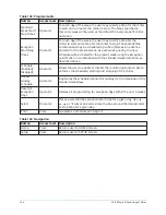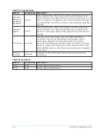
Table 141: Programmable
Button
Access level Description
Clock
(Enabled/
Disabled)
Operator
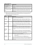
Allows the user to enable or disable the Real Time Clock in
order to conserve battery life. The clock will be disabled during
manufacturing and must be enabled at system commissioning. In
addition, when preparing for prolonged shutdown the clock should
once again be disabled. With the 031-03630-007 microboard this
setting may be changed but has no effect. The battery in the 03630
microboard will last for over 10 years.
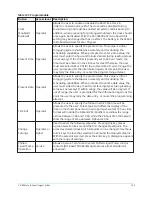
Present Time Operator
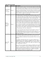
Allows the user to specify the present time. This value is critical
to logging system shutdowns accurately and for utilizing the
scheduling capabilities. When prompted to enter a time value, the
user must enter the hour and minute desired (using leading zeroes
as necessary). If the chiller is presently set to 24-hour mode, the
time must be entered in the 24-hour format. Otherwise, the user
must also select AM or PM for the entered time. If out of range, the
user is prompted for the information again. At this point the user
may retry the time entry, or cancel the programming attempt.
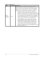
Present Date Operator
Allows the user to specify the present date. This value is critical
to logging system shutdowns accurately and for utilizing the
scheduling capabilities. When prompted to enter a date value, the
user must enter the day, month, and four-digit year (using leading
zeroes as necessary). If within range, the value will be accepted. If
out of range, the user is prompted for the information again. At this
point the user may retry the date entry, or cancel the programming
attempt.
12/24 Hr
Operator
Allows the user to specify the format in which the time will be
presented to the user. This setpoint will affect the display of the
time on the chiller panel and on all reports generated. 12-hour time
format will include the AM and PM modifiers and show the range
of time between 1:00 and 12:59, while the 24-hour time format will
show the range of time between 0:00 and 23:59.
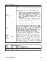
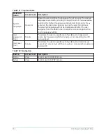
Change
Settings
Operator or
higher
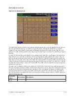
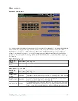
Used to enter the following setpoints. Pressing this key places
a green selection box around the first changeable setpoint. The
access level determines which setpoints can be changed. Use the ▲
and ▼ keys to place the selection box around the desired setpoint.
With the setpoint selected, press the Enter key. A dialog box appears
with the range of settings.
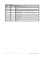
Chilled
Liquid Pump
Operation
Service
Allows a Service Technician to select Chilled Liquid Pump control
contacts (I/O Board TB2-44/45) operation as either standard or
enhanced.
145
YK-EP Style B Centrifugal Chiller
Summary of Contents for YK-EP
Page 2: ...2 YK EP Style B Centrifugal Chiller...
Page 6: ...6 YK EP Style B Centrifugal Chiller...
Page 227: ...Figure 72 Sample printout of Status 227 YK EP Style B Centrifugal Chiller...
Page 228: ...Figure 73 Sample printout of Status cont YK EP Style B Centrifugal Chiller 228...
Page 229: ...Figure 74 Sample printout of Setpoints 229 YK EP Style B Centrifugal Chiller...
Page 230: ...Figure 75 Sample printout of Setpoints cont YK EP Style B Centrifugal Chiller 230...
Page 231: ...Figure 76 Sample printout of Schedule 231 YK EP Style B Centrifugal Chiller...
Page 232: ...Figure 77 Sample printout of a Sales order YK EP Style B Centrifugal Chiller 232...
Page 233: ...Figure 78 Sample printout of a Sales order cont 233 YK EP Style B Centrifugal Chiller...
Page 234: ...Figure 79 Sample printout of History YK EP Style B Centrifugal Chiller 234...
Page 235: ...Figure 80 Sample printout of History cont 235 YK EP Style B Centrifugal Chiller...
Page 236: ...Figure 81 Sample printout of a security log report YK EP Style B Centrifugal Chiller 236...


