

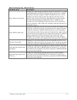


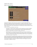
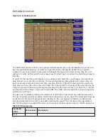
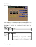

Table 137: Display only
Button
Description
Leaving Chilled Liquid
Temperature Cycling –
Restart
Displays the Leaving Chilled Liquid Temperature at which the chiller
will restart after it has shut down due to over-cooling temperature.
This value is calculated by adding the Leaving Chilled Liquid
Temperature Cycling Offset – Restart to the Leaving Chilled Liquid
Temperature – Setpoint.
Current Limit Setpoint
Displays the active Current Limit Setpoint.
In Local mode, this is the locally programmed Current Limit
Setpoint. In ISN Remote mode, this is the setpoint received from the
E-Link or SC-EQ communications interface. In Analog Remote mode,
this is the setpoint received via 0 to 10VDC, 2 to 10VDC, 0 to 20mA
or 4 to 20mA input. In Digital Remote mode, this is the Pulse width
Modulation signal input.
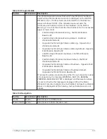
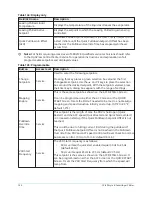
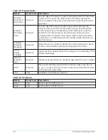
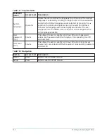
Table 138: Programmable
Button
Access level Description
Pulldown
Demand
Limit
Operator
Allows the user to specify the current limit value (as a percentage
of Full Load Amps) to which the chiller will be limited during the
specified pulldown limit time. Adjustable from 30% to 100%, Default
= 100%. This value will override the Motor Current Limit value during
this time period. This function is used to provide energy savings
following chiller start-up.
Pulldown
Demand
Time
Operator
Allows the user to set a period of time for which the pulldown
demand limit will be in effect after the chiller starts.
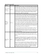
View
Generates setpoints print report.
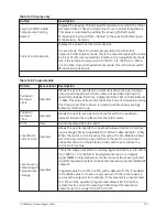
Local Motor
Current Limit Operator
Allows the user to specify the maximum allowed motor current (as
a percentage of FLA). Adjustable from 30% to 100%, Default = 100%.
When the motor current reaches this value, the Pre-Rotation Vanes
will not be permitted to open further. If the motor current rises
above this value, the Pre-Rotation Vanes will close to reduce the
current to this value.
Local Leaving
Chilled Liquid
Temperature
– Range
Operator
This is the range over which an analog signal (0 to 20 mA, 4 to 20mA,
0 to 10VDC or 2 to 10VDC) in Analog Remote mode or a digital
signal (PWM) in Digital Remote mode can reset the Leaving Chilled
Liquid Temperature Setpoint above the operator programmed BASE
Setpoint.
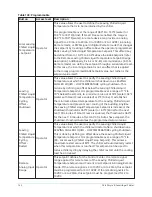
Programmable from 10°F to 40°F, with a default of 10°F, it is added
to the BASE value to create a range over which the remote device
can reset the setpoint. For example, if this setpoint is programmed
for 10°F and the operator programmed value is 45°F, then the
remote device can set the Leaving Chilled Liquid Temperature
Setpoint over the range of 45.0°F to 55.0°F.
141
YK-EP Style B Centrifugal Chiller
Summary of Contents for YK-EP
Page 2: ...2 YK EP Style B Centrifugal Chiller...
Page 6: ...6 YK EP Style B Centrifugal Chiller...
Page 227: ...Figure 72 Sample printout of Status 227 YK EP Style B Centrifugal Chiller...
Page 228: ...Figure 73 Sample printout of Status cont YK EP Style B Centrifugal Chiller 228...
Page 229: ...Figure 74 Sample printout of Setpoints 229 YK EP Style B Centrifugal Chiller...
Page 230: ...Figure 75 Sample printout of Setpoints cont YK EP Style B Centrifugal Chiller 230...
Page 231: ...Figure 76 Sample printout of Schedule 231 YK EP Style B Centrifugal Chiller...
Page 232: ...Figure 77 Sample printout of a Sales order YK EP Style B Centrifugal Chiller 232...
Page 233: ...Figure 78 Sample printout of a Sales order cont 233 YK EP Style B Centrifugal Chiller...
Page 234: ...Figure 79 Sample printout of History YK EP Style B Centrifugal Chiller 234...
Page 235: ...Figure 80 Sample printout of History cont 235 YK EP Style B Centrifugal Chiller...
Page 236: ...Figure 81 Sample printout of a security log report YK EP Style B Centrifugal Chiller 236...


