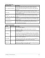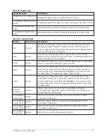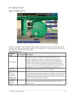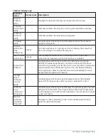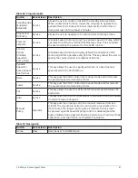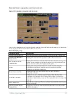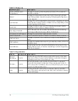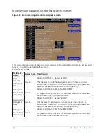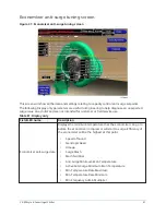
Table 69: Programmable
Button
Access level Description
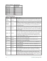
Standby Lube
(Enabled /
Disabled)
Service
Allows the user to enable or disable the standby lube operation.
When enabled, this function causes the oil pump to operate for a
period of two (2) minutes at 24 hour intervals from when the oil
pump was last run for at least 2 minutes.
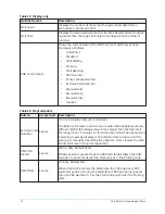
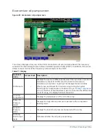
Economizer
Oil Pump
Service
Allows the user to navigate to the Economizer Oil Pump Screen.
Pressure
Setpoint
Service
(Variable Speed Oil Pump Only) The Variable Speed Oil Pump (VSOP)
operates to control to a defined Oil Pressure value. This key allows
the user to define the setpoint for the VSOP control.
Control
Period
(Variable
Speed Oil
Pump Only)
Service
(Variable Speed Oil Pump Only) By default, the automatic VSOP
control algorithm operates every 300 ms. This key allows the user to
specify the control period in multiples of 300 ms.
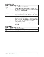
Variable
Speed Oil
Pump Speed
Control: Set
Service
This key allows the user to specify automatic or a fixed manual
speed at which the VSOP will run.
Raise
Service
This key puts the VSOP control into manual mode and increments
the present speed command by 0.5 Hz.
Lower
Service
This key puts the VSOP control into manual mode and decrements
the present speed command by 0.5 Hz.
Set
Service
This key allows the user to set the VSOP manual speed between 25
and 60 Hz .
Auto
Service
This key returns the VSOP to automatic mode where control is based
on the Oil Pressure Setpoint.
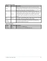
Manual
Pump
Operator
This key puts the oil pump control in manual mode and forces it
to RUN. The oil pump is limited to running for a maximum of ten
(10) minutes. If a longer running time is desired, this key must
be pressed again. Manual Oil Pump control is disabled (and the
button hidden) during System Prelube, System Run, Proximity Probe
Calibration, Seal Lubrication, and System Coastdown.
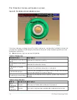
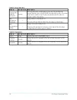
Table 70: Navigation
Button
Access level Description
Home
View
Returns user to HOME Screen.
81
YK-EP Style B Centrifugal Chiller
Summary of Contents for YK-EP
Page 2: ...2 YK EP Style B Centrifugal Chiller...
Page 6: ...6 YK EP Style B Centrifugal Chiller...
Page 227: ...Figure 72 Sample printout of Status 227 YK EP Style B Centrifugal Chiller...
Page 228: ...Figure 73 Sample printout of Status cont YK EP Style B Centrifugal Chiller 228...
Page 229: ...Figure 74 Sample printout of Setpoints 229 YK EP Style B Centrifugal Chiller...
Page 230: ...Figure 75 Sample printout of Setpoints cont YK EP Style B Centrifugal Chiller 230...
Page 231: ...Figure 76 Sample printout of Schedule 231 YK EP Style B Centrifugal Chiller...
Page 232: ...Figure 77 Sample printout of a Sales order YK EP Style B Centrifugal Chiller 232...
Page 233: ...Figure 78 Sample printout of a Sales order cont 233 YK EP Style B Centrifugal Chiller...
Page 234: ...Figure 79 Sample printout of History YK EP Style B Centrifugal Chiller 234...
Page 235: ...Figure 80 Sample printout of History cont 235 YK EP Style B Centrifugal Chiller...
Page 236: ...Figure 81 Sample printout of a security log report YK EP Style B Centrifugal Chiller 236...

