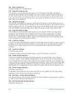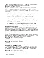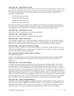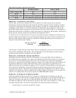
VSD – Harmonic Filter-DC Bus Voltage Imbalance
If the Half DC Link Voltage does not remain within plus or minus 63VDC of the DC Link Voltage
divided by 2, this shutdown is performed.
Harmonic Filter – Input Current Overload
The three phases of RMS Filter current are monitored. If any one of the three phases continuously
exceeds a given threshold for 7 seconds, a chiller shutdown is performed and this message is
displayed. The maximum permissible continuous RMS current ratings for the Harmonic Filter are:
•
351/292 HP equals 128 Amps
•
503/419 HP equals 176 Amps
•
790/658 HP equals 277 Amps
•
1048/917 HP equals 385 Amps
Harmonic Filter – Logic Board Power Supply
The low voltage power supplies on the Filter Logic Board have decreased below their permissible
operating range. The Filter Logic Board receives its power from the VSD Logic Board via the ribbon
cable, connecting the two boards.
Harmonic Filter – Run Signal
When a digital run command is received at the Filter Logic Board from the VSD Logic Board via
the 16 position ribbon cable, a 1/10 second timer is started. If a redundant run command does
not occur on the serial data link from the VSD Logic Board before the timer expires, a shutdown is
performed and this message is generated.
Harmonic Filter – DC Current Transformer 1
During initialization, with no current flowing through the DC Current Transformers (DCCT’s), the
DCCT output voltages are measured and compared with a preset limit via the Filter Logic Board. If
the measured values exceed the preset limits, the DCCT’s are presumed to be defective and this
shutdown is generated.
Harmonic Filter – DC Current Transformer 2
See
Harmonic Filter – DC Current Transformer 1
message above.
Safety shutdown messages
Evaporator – Low Pressure
The Evaporator Pressure, as sensed by the Evaporator transducer, has decreased to the safety
shutdown threshold. For water cooling applications, the safety shutdown threshold is a fixed value
for the respective refrigerant. For Brine cooling applications, the safety shutdown threshold varies
according to the concentration of the Brine solution. The Brine shutdown threshold is programmed
at the YORK Factory. It should not be changed by anyone other than a qualified Service Technician
following instructions in
OptiView Control Center – Service Instructions (Form 160.54-M1)
. The chiller
can be started after the Evaporator Pressure increases to the restart threshold and the Compressor
Switch is placed in the Stop-Reset (O) position.
YK-EP Style B Centrifugal Chiller
208
Summary of Contents for YK-EP
Page 2: ...2 YK EP Style B Centrifugal Chiller...
Page 6: ...6 YK EP Style B Centrifugal Chiller...
Page 227: ...Figure 72 Sample printout of Status 227 YK EP Style B Centrifugal Chiller...
Page 228: ...Figure 73 Sample printout of Status cont YK EP Style B Centrifugal Chiller 228...
Page 229: ...Figure 74 Sample printout of Setpoints 229 YK EP Style B Centrifugal Chiller...
Page 230: ...Figure 75 Sample printout of Setpoints cont YK EP Style B Centrifugal Chiller 230...
Page 231: ...Figure 76 Sample printout of Schedule 231 YK EP Style B Centrifugal Chiller...
Page 232: ...Figure 77 Sample printout of a Sales order YK EP Style B Centrifugal Chiller 232...
Page 233: ...Figure 78 Sample printout of a Sales order cont 233 YK EP Style B Centrifugal Chiller...
Page 234: ...Figure 79 Sample printout of History YK EP Style B Centrifugal Chiller 234...
Page 235: ...Figure 80 Sample printout of History cont 235 YK EP Style B Centrifugal Chiller...
Page 236: ...Figure 81 Sample printout of a security log report YK EP Style B Centrifugal Chiller 236...

