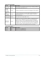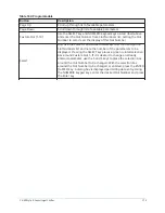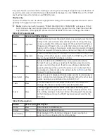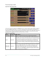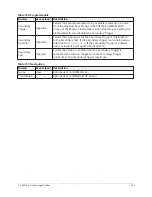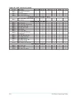
Table 187: Programmable
Button
Access level Description
Data Point
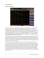
Min (1-6)
Operator
Only displayed if the Associated Slot Number is not Zero. This is
the minimum value displayed for the Y-Axis. Selecting a parameter
for a Data Point sets this to the default value, which is the lowest
value allowed for that parameter. It can be changed to a value that
provides a more appropriate resolution for the parameter being
monitored. To change, use the SELECT key as described above and
enter the desired value. The value must always be set to a value less
than the Data Point Max. Otherwise, a red graph is displayed on the
TREND Screen with the words TREND MAX MUST BE > TREND MIN.
If the parameter selected for this data point is a digital type (on/off),
this value must be set to zero (0). Zero indicates the OFF state.
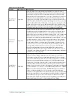
Collection
Interval
Operator
Selects the interval at which the parameters are sampled. There
are 450 data points displayed across the X-Axis of the graph. Each
point represents the instantaneous value of the parameter. The
user selects the time interval between these points. This is called the
Data Collection Interval, or the interval at which the parameter is
sampled. This interval is programmable over the range of 1 second
to 3600 seconds (1 hour), in one second increments. The selected
interval not only determines the sample interval, but also the full
screen time display. The full screen time display is a result of the
selected interval in seconds, multiplied by the 450 data points. For
example, if the Data Collection Interval is programmed for 900
seconds, the parameter would be sampled every 900 seconds,
with the last 112.5 hours (4.7 days) of data viewable on the screen.
Therefore, the selected interval is a compromise between resolution
and full screen time display*.
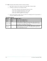
Data Point
Max (1-6)
Operator
Only displayed if the associated Slot Number is not zero. This is the
maximum value displayed for the Y-Axis. Selecting a parameter
for a Data Point sets this to the default value, which is the highest
value allowed for that parameter. It can be changed to a value that
provides a more appropriate resolution for the parameter being
monitored. To change, use the SELECT key as described above and
enter the desired value. The value must always be set to a value
greater than the Data Point Min. Otherwise, a red graph is displayed
on the TREND Screen with the words TREND MAX MUST BE > TREND
MIN. There are 20 Y-Axis divisions. If a MIN-MAX span is selected
that is not evenly divided by 20, the program will automatically
select the next higher MAX value that makes the span evenly divided
by 20. For example, if 0.0 is selected as the MIN and 69.0 is selected
as the MAX, the program will insert 70.0 as the MAX value. If the
parameter selected for this data point is a digital type (on/off), this
value must be set to one (1). One indicates the on state.
179
YK-EP Style B Centrifugal Chiller
Summary of Contents for YK-EP
Page 2: ...2 YK EP Style B Centrifugal Chiller...
Page 6: ...6 YK EP Style B Centrifugal Chiller...
Page 227: ...Figure 72 Sample printout of Status 227 YK EP Style B Centrifugal Chiller...
Page 228: ...Figure 73 Sample printout of Status cont YK EP Style B Centrifugal Chiller 228...
Page 229: ...Figure 74 Sample printout of Setpoints 229 YK EP Style B Centrifugal Chiller...
Page 230: ...Figure 75 Sample printout of Setpoints cont YK EP Style B Centrifugal Chiller 230...
Page 231: ...Figure 76 Sample printout of Schedule 231 YK EP Style B Centrifugal Chiller...
Page 232: ...Figure 77 Sample printout of a Sales order YK EP Style B Centrifugal Chiller 232...
Page 233: ...Figure 78 Sample printout of a Sales order cont 233 YK EP Style B Centrifugal Chiller...
Page 234: ...Figure 79 Sample printout of History YK EP Style B Centrifugal Chiller 234...
Page 235: ...Figure 80 Sample printout of History cont 235 YK EP Style B Centrifugal Chiller...
Page 236: ...Figure 81 Sample printout of a security log report YK EP Style B Centrifugal Chiller 236...

