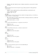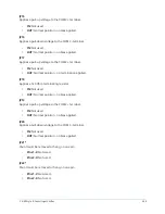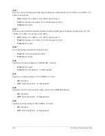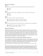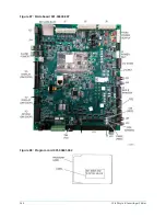
Program switches
SW1-1*
Refrigerant Selection. Must be set according to the refrigerant type installed in the chiller.
•
ON –
R-134a
•
OFF –
R22
SW1-2*
Liquid Type. Must be set according to whether the chiller is cooling water or brine solution.
•
ON –
Brine.
•
OFF –
Water.
SW1-3*
Diagnostics. Enables or Disables the software diagnostics.
•
ON –
Enables diagnostics. Disables normal chiller operation.
•
OFF –
Disables diagnostics. Enables normal chiller operation.
SW1-4
Boot from SD Card/Flash (This performs the same function as the JP6 jumper on the 02430 board.
•
ON –
Enables boot from SD card to load a new program.
•
OFF –
Boot the program stored in memory.
Keypad interface
The keypad is read via J18. The keypad is a matrix of conductors arranged in rows and columns
(Refer to
Form 160.54-M1
). There are 4 rows and 8 columns. When a key is pressed, the conductors
are pressed together at that point, creating continuity between the row conductor and the column
conductor. The keypad is read by applying a logic low to a row while l5VDC pull-up on all
other rows. The microprocessor then reads the 8 columns. If any column has a logic low on it, the
key corresponding to that coordinate (row, column) is being pressed. The microprocessor reads
the entire keypad by repeating this routine beginning with row 1 and ending with row 4. The entire
keypad is continually read while the Control Center is powered.
CM-2 board or Style A Solid State Starter interface
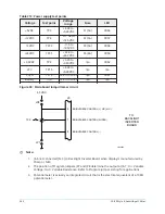
The microboard retrieves certain operating parameters (via J10) from the compressor motor starter
control board (CM-2 Current Board for Electro-Mechanical Starter or Style A Solid State Starter Logic
Board). Refer to
Form 160.54-M1
for a detailed explanation of each board. Both boards contain an 8
channel multiplexer. The microprocessor sequentially and continually reads channels 0 through 7.
It reads each channel by applying a 3-bit binary address to the multiplexer.
A 0 to 5VDC analog value is re-turned from each channel. The function of each is shown in Table
211.
The microprocessor determines which board, and therefore which starter is present, by the value
returned from channel 0. Since channels 0 through 6 are grounded, the CM-2 board returns a
0VDC value. The Solid State Starter Logic Board returns a value greater than 0.41VDC to +5VDC. If
the value is less than 0.4VDC, it indicates the starter is an Electro-mechanical (EM) starter and the
microprocessor then reads channel 7 to retrieve the peak motor current value. A value greater than
247
YK-EP Style B Centrifugal Chiller
Summary of Contents for YK-EP
Page 2: ...2 YK EP Style B Centrifugal Chiller...
Page 6: ...6 YK EP Style B Centrifugal Chiller...
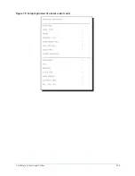
Page 227: ...Figure 72 Sample printout of Status 227 YK EP Style B Centrifugal Chiller...
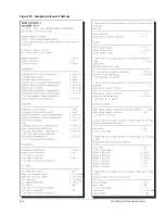
Page 228: ...Figure 73 Sample printout of Status cont YK EP Style B Centrifugal Chiller 228...
Page 229: ...Figure 74 Sample printout of Setpoints 229 YK EP Style B Centrifugal Chiller...
Page 230: ...Figure 75 Sample printout of Setpoints cont YK EP Style B Centrifugal Chiller 230...
Page 231: ...Figure 76 Sample printout of Schedule 231 YK EP Style B Centrifugal Chiller...
Page 232: ...Figure 77 Sample printout of a Sales order YK EP Style B Centrifugal Chiller 232...
Page 233: ...Figure 78 Sample printout of a Sales order cont 233 YK EP Style B Centrifugal Chiller...
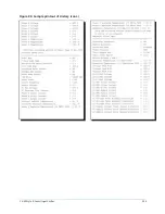
Page 234: ...Figure 79 Sample printout of History YK EP Style B Centrifugal Chiller 234...
Page 235: ...Figure 80 Sample printout of History cont 235 YK EP Style B Centrifugal Chiller...
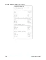
Page 236: ...Figure 81 Sample printout of a security log report YK EP Style B Centrifugal Chiller 236...

