


Analog inputs
System pressures, in the form of analog DC voltages, are input from Pressure Transducers. Refer
to
Form 160.54-M1
for more details. Formulas and graphs are included to calculate the expected
transducer output voltage for a given pressure input.
System temperatures, in the form of analog DC voltages, are input from thermistors. Refer to
Form
160.54-M1
for more details. Included are tables to convert the expected output voltage for any
temperature applied to the thermistor.
Flow switch
The chillers are supplied with factory-mounted Flow Sensors on the evaporator and condenser.
These are electronic thermal-type sensors. The operating principle of the sensor is thermal
conductivity. It uses the cooling effect of a flowing liquid to sense flow. The temperature of the
heated sensor tip is sensed by a thermistor located in the tip. A second thermistor, located higher
in the tip in a non-heated area, is only affected by changes in liquid temperature. The temperatures
sensed by the thermistors are compared. Flowing liquid carries heat away from the heated sensor
tip, lowering its temperature. The higher the flow rate, the lower the tip temperature and therefore
a lower differential between thermistors. Lower flow rates remove less heat from the tip allowing
a higher tip temperature. The lower the flow, the greater the differential between thermistors. The
sensor is vendor-calibrated to turn ON its output at a flow rate of 20cm (0.6 ft.)/second.
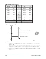
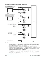
The sensor operates from a 24VAC power source and has a solid state relay output. On each sensor,
one side of the solid state relay (pin 4) is connected to +5VDC on the microboard and the other
side (pin 2) is connected to an Analog Input of the microboard (Refer to
Form 160.54-M1
for more
details). After power is applied, there is a thermal warm-up period of up to 20 seconds. During this
time, the output could be unstable. When the setpoint (or greater) flow rate is sensed, the solid
state relay output is turned ON causing it to conduct current through the 7.5K ohm Microboard
load resistor to the +5VDC. This applies greater than +4VDC to the microboard input. When a flow
rate less than the setpoint is sensed, the solid state relay output is turned OFF, resulting in no
conduction through the load resistor. This applies less than 1VDC to the microboard input. To
determine the state of the solid state relay, first confirm that +5VDC is present at pin 2 of the flow
sensor. Then connect a voltmeter between the microboard TP1 (GND) and the respective flow
sensor input to the microboard.
The software accommodates either the Paddle type sensors connected to TB4 of the I/O Board or
the Thermal type sensors connected to J14 on the microboard. To assure the program reads the
correct input, the Flow Switch setpoint on the OPERATIONS Screen must be set appropriately .
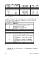
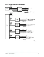
Serial data ports
Microboard 031-03630-007 is equipped with 6 serial ports. Each port is dedicated for a specific
function as follows:
1. COM1 (J2) – RS-232. Printer.
2. COM2 (J13) – RS-485. Modbus communications to the Primary Liquid Cooled Solid State
Starter, Medium Voltage Solid State Starter, Medium Voltage Variable Speed Drive or Variable
Speed Drive.
3. COM3 (J12) – RS-485. LTC I/O and Motor Monitoring.
4. COM4 (J2) – RS-232. SC-EQ communication card.
5. COM5B (TB4) – RS-485. Future VGD actuator.
6. COM6 J29 & J30 Fiber Optic cable to LCSSS.
Each port is equipped with two LED’s. A red TX LED illuminates as data is transmitted to or
requested from another device. A green RX LED illuminates as data is received from another device.
YK-EP Style B Centrifugal Chiller
250
Summary of Contents for YK-EP
Page 2: ...2 YK EP Style B Centrifugal Chiller...
Page 6: ...6 YK EP Style B Centrifugal Chiller...
Page 227: ...Figure 72 Sample printout of Status 227 YK EP Style B Centrifugal Chiller...
Page 228: ...Figure 73 Sample printout of Status cont YK EP Style B Centrifugal Chiller 228...
Page 229: ...Figure 74 Sample printout of Setpoints 229 YK EP Style B Centrifugal Chiller...
Page 230: ...Figure 75 Sample printout of Setpoints cont YK EP Style B Centrifugal Chiller 230...
Page 231: ...Figure 76 Sample printout of Schedule 231 YK EP Style B Centrifugal Chiller...
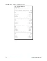
Page 232: ...Figure 77 Sample printout of a Sales order YK EP Style B Centrifugal Chiller 232...
Page 233: ...Figure 78 Sample printout of a Sales order cont 233 YK EP Style B Centrifugal Chiller...
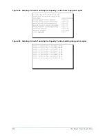
Page 234: ...Figure 79 Sample printout of History YK EP Style B Centrifugal Chiller 234...
Page 235: ...Figure 80 Sample printout of History cont 235 YK EP Style B Centrifugal Chiller...
Page 236: ...Figure 81 Sample printout of a security log report YK EP Style B Centrifugal Chiller 236...


